Download
1 / 27
270 likes | 447 Views
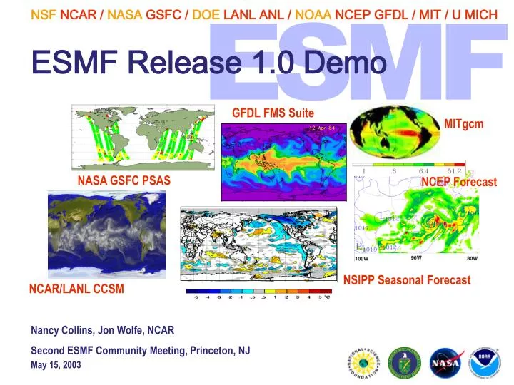
ESMF Release 1.0 Demo. GFDL FMS Suite. MITgcm. NASA GSFC PSAS. NCEP Forecast. NSIPP Seasonal Forecast. NCAR/LANL CCSM. Nancy Collins, Jon Wolfe, NCAR Second ESMF Community Meeting, Princeton, NJ. Outline. ESMF Demo Structure ESMF Demo Data and Control Flow

E N D
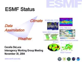
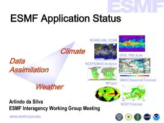
ESMF Release 1.0 Demo GFDL FMS Suite MITgcm NASA GSFC PSAS NCEP Forecast NSIPP Seasonal Forecast NCAR/LANL CCSM Nancy Collins, Jon Wolfe, NCAR Second ESMF Community Meeting, Princeton, NJ
Outline • ESMF Demo Structure • ESMF Demo Data and Control Flow • Examples of ESMF Usage in Demo Code • ESMF Demo Output
ESMF Demo Overview • One Component Calculates Compressible Flow around Obstacles, with energy equation (FlowSolverMod). Initial Flow is left to right over heated Obstacles. • Second Component Calculates Injector properties (InjectorMod), coupled to FlowSolver. • Similar to river run-off into an Ocean model.
Demo Component Structure All code in these files is user-written code, not part of the ESMF Framework. Demo Application Component Demo Gridded Component Injector Gridded Component 2-way Coupler Component Solver Gridded Component
Component Control Flow The red arrows show execution ordering. Coupler Injector Solver Export State Import State CPL Run Inject Run Solver Run Data Fields Data Fields CPL Run Import State Export State
Component Data Flow The green arrows show Data movement, black arrow show Data references. Coupler Injector Solver Export State Import State CPL Run Inject Run Solver Run Data Fields Data Fields CPL Run Import State Export State
Component Data Layouts Each Component has a different Layout. The coupler routes data between processing elements. Injector Coupler Solver Export State Import State Data Fields Data Fields 6x2 Layout 1x12 Layout 3x4 Layout Import State Export State
Layouts in the Demo • The demo runs 4, 8, 12 and 16-way. For the 12-way decomposition the Injector component decomposes the data in a 6x2 pattern, and the Solver uses 3x4. This is controlled by the type of Layout associated with each Component.
User code vs. ESMF code The code flow is: • Main is user-written • Creates Application Component • Creates Top level Gridded component(s) • Calls registration routine
User vs. ESMF code (cont.) • ESMF Framework provides language independent layer between calls • Framework checks arguments, supplies defaults, verifies DE Layout, calls into user code • User component code runs, fills in States, and returns error code • Returns thru Framework back to calling code
ESMF in the Application Component - Creation This example code creates the top level application component, which initializes the ESMF Framework as well. compApp = ESMF_AppCompCreate("Coupled Flow Application", rc=rc) Query application for default layout. call ESMF_AppCompGet(compApp, layout=layoutApp, rc=rc) Create the Gridded component, passing in the default layout. compGridded = ESMF_GridCompCreate("Coupled Flow Demo", & layout=layoutApp, rc=rc)
ESMF in the Application Component - Grid Init In the Demo, the Grid is created with input extents and other Grid parameters: grid = ESMF_GridCreate(i_max=i_max, j_max=j_max, & x_min=x_min, x_max=x_max, & y_min=y_min, y_max=y_max, & layout=layoutApp, & horz_gridtype=ESMF_GridType_XY, & horz_stagger=ESMF_GridStagger_C, & horz_coord_system=ESMF_CoordSystem_Cartesian, & halo_width=1, name="source grid", rc=rc) The Grid can then be attached to the Gridded Component with a Set call: call ESMF_GridCompSet(compGridded, grid=grid, rc=rc)
ESMF in the Application Component - Clock Init call ESMF_CalendarInit(gregorianCalendar, ESMF_CAL_GREGORIAN, rc) call ESMF_TimeIntervalInit(timeStep, S=int(2,kind=ESMF_IKIND_I8), rc=rc) call ESMF_TimeInit(startTime, YR=int(2003,kind=ESMF_IKIND_I8), & MM=s_month, DD=s_day, H=s_hour, M=s_min, & S=int(0,kind=ESMF_IKIND_I8), & cal=gregorianCalendar, rc=rc) call ESMF_TimeInit(stopTime, YR=int(2003,kind=ESMF_IKIND_I8), & MM=e_month, DD=e_day, H=e_hour, M=e_min, & S=int(0,kind=ESMF_IKIND_I8), & cal=gregorianCalendar, rc=rc) call ESMF_ClockInit(clock, timeStep, startTime, stopTime, rc=rc)
ESMF in the Application Component - Init/Run/Finalize Part of a User-written Component’s integration - subroutinization into three separate callable routines: call ESMF_GridCompInitialize(compGridded, flowstate, flowstate, clock, & rc=rc) call ESMF_GridCompRun(compGridded, flowstate, flowstate, clock, rc=rc) call ESMF_GridCompFinalize(compGridded, flowstate, flowstate, clock, rc=rc)
ESMF in Components - Registry This is an example from one of the Components registering its callback routines. call ESMF_GridCompSetEntryPoint(comp, ESMF_SETINIT, Flow_Init1, 1, rc) call ESMF_GridCompSetEntryPoint(comp, ESMF_SETINIT, Flow_Init2, 2, rc) call ESMF_GridCompSetEntryPoint(comp, ESMF_SETRUN, FlowSolve, 0, rc) call ESMF_GridCompSetEntryPoint(comp, ESMF_SETFINAL, Flow_Final, 0, & rc)
ESMF in the Gridded Component - Layout Create The following code creates 2 sublayouts on the same set of PEs (processing elements) as the top level Component, but each of the sublayouts has a different connectivity: cnameIN = "Injector model" layoutIN = ESMF_DELayoutCreate(delist, 2, (/ mid, by2 /), (/ 0, 0 /), rc) INcomp = ESMF_GridCompCreate(cnameIN, layout=layoutIN, rc=rc) cnameFS = "Flow Solver model" layoutFS = ESMF_DELayoutCreate(delist, 2, (/ quart, by4 /), (/ 0, 0 /), rc) FScomp = ESMF_GridCompCreate(cnameFS, layout=layoutFS, rc=rc)
ESMF in the Gridded Component - State Create The following code creates Import and Export States for the Injector subcomponent. All information being passed to other subcomponents will be described by these States. INimp = ESMF_StateCreate("Injection Input", ESMF_STATEIMPORT, & cnameIN) INexp = ESMF_StateCreate("Injection Feedback", ESMF_STATEEXPORT,& cnameIN)
ESMF in Components - Import/Export States For initialization, add all fields to the import state. Only the ones needed will be copied over to the export state for coupling. call ESMF_StateAddData(import_state, field_sie, rc) call ESMF_StateAddData(import_state, field_u, rc) call ESMF_StateAddData(import_state, field_v, rc) This code is adding names only to the export list, marked by default as "not needed". The coupler will mark the ones needed based on the requirements of the component(s) this is coupled to. call ESMF_StateAddData(export_state, "SIE", rc) call ESMF_StateAddData(export_state, "U", rc) call ESMF_StateAddData(export_state, "V", rc)
ESMF in the Coupler - Init The Coupler sets the “is needed” flag for each Field in the Export State which will be needed by some other Component: call ESMF_StateGetData(statelist, & "Coupler States FlowSolver to Injector", flowstates, rc) call ESMF_StateGetData(flowstates, "FlowSolver Feedback", fromflow, rc) call ESMF_StateSetNeeded(fromflow, "SIE", ESMF_STATEDATAISNEEDED, rc) call ESMF_StateSetNeeded(fromflow, "V", ESMF_STATEDATAISNEEDED, rc) call ESMF_StateSetNeeded(fromflow, "RHO", ESMF_STATEDATAISNEEDED, rc) call ESMF_StateSetNeeded(fromflow, "FLAG", ESMF_STATEDATAISNEEDED, rc)
ESMF in Components - Field Creation and Array Usage In this example, we create a Field from an ArraySpec, which designates the rank, type, and kind of the data. call ESMF_ArraySpecInit(arrayspec, rank=2, type=ESMF_DATA_REAL, & kind=ESMF_KIND_R4) field_sie = ESMF_FieldCreate(grid, arrayspec, relloc=ESMF_CELL_CENTER, & name="SIE", rc=status) Once the Field has been created, we have to get a pointer to the Array inside it and then its data, called “sie.” Inside the Component "sie" can be used like an array made by an F90 allocation but will reference the data inside "field_sie." call ESMF_FieldGetData(field_sie, array_temp, rc=status) call ESMF_ArrayGetData(array_temp, sie, ESMF_DATA_REF, status)
ESMF in the Coupler - Route The following piece of code provides an example of calling Route between two Fields in the Coupler Component. The first two lines get the Fields from the States, each corresponding to a different subcomponent. One is an Export State and the other is an Import State. call ESMF_StateGetData(mysource, datanames(i), srcfield, rc=status) call ESMF_StateGetData(mydest, datanames(i), dstfield, rc=status) The Route routine uses information contained in the Fields and the Coupler Layout object to call the Communication routines to move the data. Because many Fields may share the same Grid association, the same routing information may be needed repeatedly. Route information is cached so the precomputed information can be retained. call ESMF_FieldRoute(srcfield, dstfield, cpllayout, status)
ESMF in Components - Halo The following piece of code provides an example of Haloing the data in a Field. Currently the FieldHalo routine assumes the entire Halo is updated completely; i.e. the user cannot specify halo width or side separately. FieldHalo uses the Route object to transfer data from the exclusive computational domain of one DE to the Halo region of another. call ESMF_FieldHalo(field_rhou, status)
Running the Demo • Officially supported platforms: • IBM RS/6000 64 or 32 bits • Compaq (Alpha) Tru64 • IRIX 64 bits • Binary tarballs on web page • Source tarball available also • Produces data files as output
Demo Input • Will be ESMF Config files • Is currently F90 namelist input • Separate files for Top Level Application Component, Gridded Injector Component, and Flow Solver Component • See Users Manual, Section 10, for details on the specific variables
Demo Output • Controlled by the configuration files • Every N timesteps 3 data files are produced: • SIE.nnn - Internal Energy • U.nnn - U velocity • V.nnn - V velocity • Array header information gives size of each dimension, data type. • Use your favorite Vis tool to make images