Download

1 / 29
290 likes | 388 Views
Design of a Software Correlator for the Phase I SKA. Jongsoo Kim Cavendish Lab., Univ. of Cambridge & Korea Astronomy and Space Science Institute. Collaborators: Paul Alexander (Univ. of Cambridge) Andrew Faulkner (Univ. of Cambridge)

E N D
Design of a Software Correlator for the Phase I SKA Jongsoo Kim Cavendish Lab., Univ. of Cambridge & Korea Astronomy and Space Science Institute Collaborators: Paul Alexander (Univ. of Cambridge) Andrew Faulkner (Univ. of Cambridge) Bong Won Sohn (KASI, Korea) Minho Choi (KASI, Korea) Dongsu Ryu (Chungnam Nat’l Univ., Korea)
PrepSKA • 7th EU Framework Programme • 01/04/2008 – 31/03/2011(?) • 20+11 institutions • 09/2009 Manchester WP2 meeting • AA, FPAA, WBSF • Power Issue • Correlator
Correlators for Radio Interferometry • ASIC (Application-Specific Integrated Circuit) • FPGR (Field-Programmable Gate Arrays) • Software (high level-languages, e.g., C/C++) • Rapid development • Expandability • …
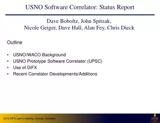
Current Status of SC • LBA (Australian Long Baseline Array) • 8 antennas (Parkes, … 22-64m, 1.4-22GHz) • DiFX software correlator (2006; Deller et al. 2007) • VLBA (Very Long Baseline Array) • 10 antennas (25m, 330MHz - 86GHz) • DiFX (2009) • GMRT (Giant Metrewave Radio Telescope) • 30 antennas (45m, 50MHz-1.5GHz), 32MHz • ASIC software correlator (Roy et al. 2010)
Current Status of SC (cont.) • LOFAR (Low Frequency Array) • LBA (Low Band Antennae) 10-90MHz • HBA (High Band Antennae) 110 – 250MHz • IBM BlueGene/P: software correlation
Phase I SKA (2013-2018) • 10% of the final collecting area • ~300 dishes • software correlator
Correlation Theorem, FX-correlator X-step (CMAC): ~ N operations per sample F-step (FT): ~log2(Nc) operations per sample
FLOPS of the X-step in FX correlator • 4 is from • 8 is from 4 multiplications and 4 additions: • N(N+1)/2 is the number of auto- and cross- correlations with antenna N • if B (bandwidth) = 4 GHz N=2 96x4 GFLOPS = 384 GFLOPS N=100 16x4x104 GFLOPS = 640 TFLOPS N=300 16x9x4x104 GFLOPS = 5.76 PFLOPS N=3000 16x9x4x106 GFLOPS = 576 PFLOPS
Fermi Streaming Multiprocessor • Fermi features several major innovations:• 512 CUDA cores• NVIDIA Parallel DataCache technology• NVIDIA GigaThread™ engine• ECC support • Performance: > 2 Tflops
Design goals • Connect antennas and computer nodes with simple network topology • Use future technology development of HPC clusters • Simplify programming
Software Correlator for Phase I SKA (‘2018) 300 nodes 100 Gb/s Ethernet CPUs+(GPUs) CPUs+(GPUs) CPUs+(GPUs) Required BW>512Gb/s =64GB/s CPUs+(GPUs) CPUs+(GPUs) >20 TFLOPS CPUs+(GPUs) 2x4x2x4GHz =64Gb/s 2 pols, 4bit sampling, Nyquist, BW
Communication between Computer Nodes I after FFT 1 Nc Node 1 FFT 2x32x2xB 2x4x2xB Node 2 FFT Nc 2
Communication between Computer Nodes II after communication 1 Nc/2 1 Node 1 FFT 2 2x32x2xB 2x4x2xB Node 2 FFT 1 2 Nc/2 2
All-to-All Communication between Computer Nodes after communication Nc/4 2x32x2xB 2x4x2xB 1 N>>1 BW(interconnect) =8 x 2x4x2xB =128B 2 Node 1 FFT 1 3 4 Node 2 FFT 2 Node 2 FFT 3 Nc/4 1 2 Node 2 FFT 4 3 4
Data Flows Node Interconnect BW: 40Gb/s (Infiniband) GPU, CMAC CPU, FFT 432bits bit/sample threads memory GPU, CMAC CPU, FFT 432bits bit/sample GPU Memory BW: 102GB/s (C1060) threads memory PCI-e BW: 8GB/s (gen2 16x)
AI (Arithmetic Intensity) • Definition: number of operations (flops) per byte • AI = 8flops/16bytes (Ri,Rj) = 0.5 AI = 32 flops/32bytes (Ri, Li, Rj, Lj) = 1.0 for 1x1 tile AI = 2.4 for 3x2 tiles • Since AIs are small numbers, correlation calculations are bounded by the memory bandwidth. • Performance: AI x memory BW (=102GB/s) Wayth+ (2009), van Nieuwpoort+ (2009)
Measured bandwidth of host-to-device (Tesla C1060) ~70% of PCI -e2 bandwidth
Performance of Tesla C1060 as a function of AI Performance is, indeed, memory-bounded. Maximum performance is about 1/3 of the peak performance.
AI for host-device and host-host • AI = (N+1) FLOP/byte N x 16 bytes (R,L) = 16 N byte 4x8xN(N+1)/2 FLOP • PCI bus bandwidth PCI-e 2.0: 8.0GB/s (15 Jan. 2007) PCI-e 3.0: 16.0GB/s (2Q 2010, 2011) PCI-e 4.0: 32.0GB/s (201?) PCI-e 5.0: 64.0GB/s (201?) • Performance [GFLOPS] = PCI BW [GB/s] x AI [FLOP/B]
Benchmark: Performance 100GF 40Gb/s IB 10GF 40Gb/s IB
Expected performance bounded by the BWs of PCI bus and interconnect
Power usage and Costing • Computer nodes • 1.4 KW, 4 K Euro for each server including 2x0.236 KW (2 GPUs) • 0.4 MW, 1.2 M Euro for 300 servers • Network Switches • 3.8 KW for IB (40Gb) 328 ports
Technology Development in 2010 • 2Q 2010, (2011): PCI-e 3rd Generation • 2Q (April) 2010: Nvida Fermi (512 cores, L1,L2 cache) • (March 29) 2010: AMD 12 core Opteron 6100 processor • (March 30) 2010: Intel 8 core Nehaem-EX Xeon processor
Software Correlator for Phase I SKA (‘2018) 300 nodes 100 Gb/s Ethernet CPUs+(GPUs) CPUs+(GPUs) CPUs+(GPUs) Required BW>512Gb/s =64GB/s CPUs+(GPUs) CPUs+(GPUs) >20 TFLOPS CPUs+(GPUs) 2x4x2x4GHz =64Gb/s 2 pols, 4bit sampling, Nyquist, BW