Download
1 / 45
460 likes | 608 Views
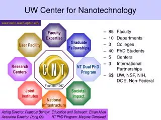
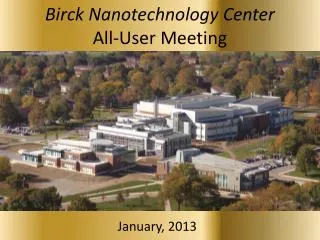
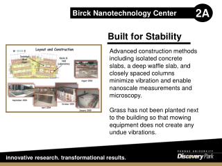
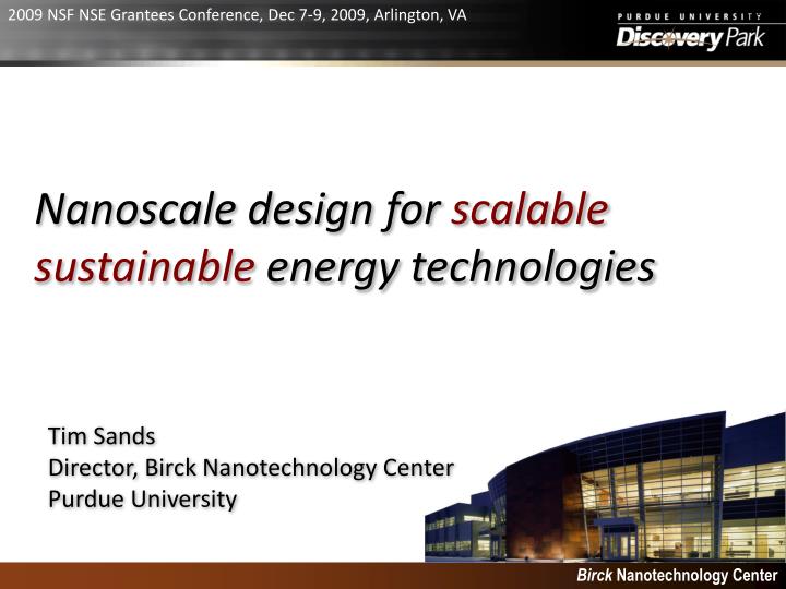
2009 NSF NSE Grantees Conference, Dec 7-9, 2009, Arlington, VA. Nanoscale design for scalable sustainable energy technologies. Tim Sands Director, Birck Nanotechnology Center Purdue University. Birck Nanotechnology Center. Themes. The magnitude of the challenge

E N D
2009 NSF NSE Grantees Conference, Dec 7-9, 2009, Arlington, VA Nanoscale design for scalable sustainable energy technologies Tim Sands Director, Birck Nanotechnology Center Purdue University Birck Nanotechnology Center
Themes • The magnitude of the challenge • The nanoscale opportunity • Focus on solid state approaches to energy efficiency • Solid state lighting • Waste heat conversion • Solid state refrigeration • Constraining the problem – filling the gap between basic and applied research • What is the technological discontinuity to be bridged? • What fundamental problem is to be solved? • Are the source materials abundant and of low toxicity? • Is there potential for scalable manufacturing? • Are there near-term niche application for early solutions?
The Terawatt Challenge Primary source for 2003 data: International Energy Agency Adapted from Richard Smalley’s presentation on “Our Energy Challenge” at the 2004 International Electron Devices Meeting (IEDM), San Francisco, CA 12/14/04
Spectrum of opportunities for nano Workshop on Nanotechnologies for Thermal and Solar Energy Conversion and Storage, August 10,11, 2008, Jacksonville, FL “Nanoscale design to enable the revolution in renewable energy” J. Baxter, Z. Bian, G. Chen, D. Danielson, M.S. Dresselhaus, A.G. Fedorov, T.S. Fisher, C.W. Jones, E. Maginn, U. Kortshagen, A. Manthiram, A. Nozik, D.R. Rolison, T. Sands, L. Shi, D. Sholl and Y. Wuo, Energy & Environmental Science 2 (2009) 559-588. Portfolio of solar/thermal/electrochemical energy conversion, storage, and conservation technologies, and their interactions
The solid-state part of the solution… • More efficient devices for… • LED-based lighting • Thermoelectric refrigeration • Thermoelectric and thermophotovoltaic conversion of waste heat • Photovoltaic conversion of solar energy and production of hydrogen • Added benefits • Compact • Robust • Low environmental impact • Challenges • Efficiency breakthroughs needed! • Availability and price of raw materials • Manufacturing costs Nanostructured semiconductors? Thin films instead of bulk? “Bottom-up” nanofabrication?
New degrees of freedom in nanocomposites • Length scales on the order of electron, phonon and photon wavelengths, and scattering lengths of electrons, phonons and electron spin • Dimensions below critical values for relaxation of lattice misfit strain and epitaxial stabilization of high pressure phases • High surface (interface)-to-volume ratios for sensing, catalysis, and chemical storage 5 nm diameter CdSe nanocrystal (Manna et al., J. Cluster Sci. 2002) Strain relaxation in nanowire heterostructures (Ertekin et al., JAP,2005) Nanoparticles suspended in solution (Frankel, MIT) Fundamentally new materials with new properties
Solid state lighting – the opportunity • Electricity generation accounts for about 37% of primary energy consumption in the U.S.* • Lighting accounts for 22% of the nation’s electric power usage. • The DoE SSL Goal: a solid-state lamp that is more efficient, longer lasting and cost competitive compared to conventional technologies, targeting a system efficiency of 50% and the color quality of sunlight. • Implications of Success: 33% reduction in energy consumed for lighting by 2025, eliminating need for 41 1000MW power plants, and saving consumers $128 B+. +Navigant Consulting (11/03) *Annual Energy Outlook (02)
LEDs – the technological discontinuity III-V LEDs cover the visible spectrum, but not with one materials system Low cost solution: Blue (In,Ga)N LED with partially absorbing yellow phosphor Limitations: poor color rendering, low efficiency due to Stokes shift Warm light solution: Board-level integration of (In,Ga)N/yellow phosphor and (Al,Ga,In)P red LEDs Limitations: “green gap”, high cost of assembly Compound Semiconductor, June 2008, pg. 17
The nano aspect of a solution? • Elastic relaxation of lattice misfit strain • Reduced electric field in recombination volume • Higher local injection current densities without Auger recombination • Greater InN incorporation, longer emission wavelengths • Filtering of threading dislocations • Lower-cost, larger diameter, higher thermal conductivity substrates (metallized silicon) • Improved geometry for light extraction EL EDS TEM
Waste heat factoids… • >60% of primary energy consumed is dissipated as waste heat • Energy costs account for approximately 8~12% of the total cost of glass production, and about 15% for steel* • The world’s data centers are projected to surpass the airline industry as a greenhouse gas polluter by 2020** • About 40 percent of the energy content of gasoline burned in automobile IC engines is lost as exhaust heat and another 30 percent is lost through engine cooling*** www.greencarcongress.com/thermoelectrics www.eere.doe.gov *http://www1.eere.energy.gov/industry/program_areas/industries.html **Study by McKinsey & Co., Green Enterprise Computing Symposium in Orlando, Fla., May 1, 2008 ***http://www.washingtontimes.com/news/2008/aug/12/researchers-eye-exhaust-for-fuel/?page=2
Overview: thermoelectrics • Thermoelectric primer • Recent progress in ZT enhancement by nanostructuring (MBE and bulk) • A scalable approach with nanoscale control: electrodeposition into porous templates • Mitigating parasitics – removing/replacing the template, and scaling to thicknesses > 100 mm • TE element fabrication from nanoscale materials
Physical basis of thermoelectricity • Thermoelectricity arises from the difference between the average energy of the electrons (or holes) responsible for conduction and the Fermi energy In an n-type semiconductor… Energy Fermi-Dirac Occupation Function Average energy of conduction electrons = * EF Density of Occupied States Density of States (DOS) 0 1
The Seebeck effect (1821) Hot Side Cold Side Initial Steady State e ] qDVoc • Generation of voltage along a conductor subjected to a temperature difference • Initially, carriers (electrons or holes) move from hot to cold • Resulting potential difference opposes further current flow • Open circuit voltage is proportional to DT where S is the Seebeck coefficient [V/K] • Completing the circuit through a load generator lim {DVoc}= SDT DT0 Electron energy
Thermoelectric generators zT = S2sT/k Dimensionless figure-of-merit Altenkirch (1909,1911) • Large Seebeck coefficient (S) large open circuit voltage for generators; large Peltier coefficient for refrigerators • Low thermal conductivity (k) easier to maintain DT for generators; reduced conduction of heat back to cold side for refrigerators • High electrical conductivity (s) reduced Joule heating
Applications of TE today (zT ~ 1) Materials zT~1; System ZT~0.7 Thermoelectric modules • Radioisotope TE generators powering deep space probes • Automotive seat coolers/heaters (500,000/yr) • Picnic coolers • DNA PCR precision temperature cyclers • Temperature stabilizers for laser diodes used in fiber optic communications systems • Electronics cooling at the cabinet level • Remote power generators in harsh environments Heat source (PuO2) http://www.its.caltech.edu/~jsnyder/thermoelectrics/ Can we expect more from thermoelectrics? Bell, L 2008, “Cooling, heating, generating power, and recovering waste heat with thermoelectric systems,” Science 321, p.1457
Applications of TE tomorrow (zT =2-3) Materials zT=2-3; System ZT~1.5-2 • Exhaust waste heat recovery for gasoline and diesel engines to improve mileage by 10% • Cogenerators for 5-20 kW diesel generators, improving system efficiency by 5-10% • Split-spectrum solar generators (PV + TE) • Industrial waste heat recovery in metal, glass and cement processing • Flex fuel powered small engines • Microprocessor cooling • Greenhouse-gas-free HVAC for vehicles and residences Bell, L 2008, “Cooling, heating, generating power, and recovering waste heat with thermoelectric systems,” Science 321, p.1457
Materials design challenges S2 T zT = S2 zT = Lo + (kph/sT) k = ke + kph = (LosT) + kph For most bulk materials… • Increasing s increases ke (Weideman-Franz-Lorenz Law) • Decreasing kph by adding defects decreases mobility (and s) • Reducing m* increases mobility (and s), but decreases S • Increasing carrier concentration decreases S
Device design challenges • CTE and CTE mismatch • Assembly of 10s to 100s of p-n couples – electrically in series to match load resistance • Thermal and electrical parasitic resistances • Contact resistance – leg length should be greater than ~200 mm (total contact resistance <10% of total resistance for rc = 1 x 10⁻⁶ W-cm2 and rTE = 1 mW-cm) • Maintaining DT – leg length should be between ~100 mm and 1 mm to maximize power density
20% efficient TE generators? Target: >20% efficiency; >104 W/m2 power density • ZT > 2; DT ~ 500K; 10% areal coverage; forced convection
Optimum leg length Mayer and Ram, Nano-Microscale Thermophys Eng, 10 (2006) 103 Interface limited 102 Heat flux limited 101 Power density (W/cm2) 100 10-1 10-2 10 1000 100 L (µm) Leg length for maximum power density decreases with increasing heat transfer coefficient, minimizing use of less abundant materials
Design of bulk thermoelectrics S2 T ZT = • Power factor, S2s, optimized for degenerate semiconductors • Heavy masses, low “spring constants”, and large unit cells to reduce kph • Solid-solution alloying to reduce kph “Phonon glass, electron crystal” Bi2Te3 and its alloys for cooling near room temperature
Materials zT Sb1.5Bi0.5Te3 State-of-the-art commercial and NASA TE materials (from G.J. Snyder and E.S. Toberer, Nat. Mater. 7 (2008) 105.) Commercial bulk materials (not intentionally nanostructured) are limited to materials zT of ~ 1
Quantum confinement…the solution? Hicks and Dresselhaus, PRB 47 (1993) 12727 Ideal DOS: delta function several kT from EF will maximize power factor if mobility can be enhanced by eliminating ionized impurity scattering Sph 15 Bi2Te3 After Esaki, 1990 10 well Figure-of-Merit ZT 1D - quantum wire 5 Electron Energy 2D - quantum well 3D - bulk wire 0 0 1 2 3 4 5 6 bulk Well or Wire Width [nm] Does not include deleterious interface or barrier effects! Density of States
zT enhancement: p-type leg, 300-400K • 1950’s to 2000: Bulk (Bi,Sb)2Te3 with zT~1 • 2001: RTI group reports zT = 2.4 for Bi2Te3/Sb2Te3 superlattice grown by MBE1 • 2008: Boston College/GMZ/Nanjing/MIT group reports ball milled (Bi,Sb)2Te3 bulk alloy with nanoscale grain size yielding zT ~ 1.4 at 373K2 • 2009: Wuhan/Clemson group reports zT ~ 1.56 at 300K for melt spun and spark plasma sintered bulk (Bi,Sb)2Te3 with nanocrystalline grains embedded in amorphous matrix3 [1] Venkatasubramanian, Nature 413(2001)597 [2] Poudel, Science 320(2008)634 [3] Xie et al. APL 94 (2009)102111
Is zT > 2 possible for a scalable material? • Common thread: zT > 1 achieved by enhancing scattering of longer wavelength (> 1 nm) phonons, suppressing lattice thermal conductivity without reducing power factor • zT > 2 only reached in MBE material; difficult to scale to optimal leg lengths of 200 mm to ~1 mm • Is there a synthesis approach that combines control of vapor deposition with scaling to practical leg lengths to achieve zT > 2? • Can we enhance the power factor (S2s) as well?
Electrodeposited nanowire arrays? • Nanoscale control of grain size and composition modulation (lateral and radial) with a scalable synthesis technique • First electrodeposited Bi2Te3 nanowire (~280 nm dia.) arrays into porous anodic alumina (Sapp et al., 1999) 40 nm diameter Bi2Te3 nanowires electrodeposited into porous anodic alumina (Prieto et al., 2001) Texture control Sapp, Lakshmi, and Martin, Advan. Mater. 11(1999) 402; Prieto et al., JACS123 (2001) 7160.
(Potential) advantages of nanowires • Phonon scattering - Phonon scattering from free surfaces and grain boundaries decreases the lattice contribution to the thermal conductivity, thereby increasing zT. • Lateral elastic relaxation - Lateral elastic relaxation of strain in nanowires enables coherent interfaces in large lattice misfit heterostructures. • Elastic compliance - Improved elastic compliance resulting from free surfaces and/or interfaces with compliant matrix materials. • Chemical modification of free surfaces - Access to free surfaces permits chemical modification that may enhance charge mobility while suppressing phonon transport; short diffusion lengths less grain growth • Crystallographic texture control – interface energy driven • Quantum confinement – Potential for power factor enhancement, but only for nanowires with diameters < 5 nm (for Bi2Te3)
Challenges of nanowire topology • Minimizing parasitics • Leg lengths > 100 mm – thicker than typical PAA • Minimizing matrix thermal shunt – kmatrix <<kTE and/or matrix volume fraction, fmatrix, should be as small as possible • Enhancing mechanical strength and toughness • Protecting internal (nanowire) surfaces • Making ohmic contacts • …
Bi2Te3 nanowires – property measurements • Wang et al. (JAP 96 2004) – arrays, PAA removed • 50 nm diameter • S = 270 mV/K at 300K; Semiconducting • Zhou et al. (APL 87 2005) – single nanowires • 43.5-120 nm diameter • Highly variable S and s; k lower than bulk by 28-57% • Li et al. (Nanotech. 17 2006) – arrays, PAA removed • 40-60 nm diameter • Semiconducting • Mavrokefalos et al. (JAP 105 2009) – single nanowires • 52 and 55 nm diameter • zT estimated to be 0.1 at 400K; Doping level too high; minimal reduction (~20%) in k due to surfaces and grain boundaries; better control of stoichiometry needed Mavrokefalos et al.(JAP 2009) No power factor or ZT measurements of alloy nanowires yet
Minimizing matrix effects • Approach 1 – replace PAA matrix with low k polymer • Approach 2 – eliminate matrix by synthesizing self-supporting nanowire arrays 5 mm
PAA replacement with SU-8 • PAA selectively etched in 3 wt% KOH for 24h; rinsed with water and then IPA • SU-8 2005 spin coated at 2000 rpm to thickness of 40 mm; uv exposed, then hard baked on hot plate at 150°C Free-standing NW array NW array in PAA SU-8 backfilled NW array Etch PAA SU-8 infiltration K.G. Biswas, T.D. Sands, B.A. Cola and X. Xu, APL 94 (2009) 223116
Bi2Te3/SU-8 composite 5 m 5 m FESEM images of fractured composite in cross-section Bi2Te3 NWs cleavage plane 500 nm K.G. Biswas, T.D. Sands, B.A. Cola and X. Xu, APL 94 (2009) 223116
Photoacoustic measurement of k Replacement of PAA with SU-8 reduces the matrix penalty in ZT from 27% to ~5%. The effect will be larger with lower kTE K.G. Biswas, T.D. Sands, B.A. Cola and X. Xu, APL 94 (2009) 223116 *data from product literature
Composition modulation in Bi2(Te,Se)3 By varying the electrodeposition potential from +40 mV to -60 mV, the composition was varied from 0.18 to 0.07 mole fraction Bi2Se3. Thermal Conductivity Measurements Cross-section FESEM image of composition-modulated Bi2(Te,Se)3 nanowires. • Substantial suppression of apparent thermal conductivity • Compare to minimum of 0.31 for Bi2Te3 and ~0.20 for (Bi,Sb)2Te3[Chiritescu et al., JAP 106 (2009)] 0.2 SU-8 Thermal conductivity measurements obtained by the photoacoustic technique (Baratunda Cola, Xianfan Xu; Purdue University).
Next step… • Can we eliminate the matrix altogether? • Suggests interconnected, self-supporting nanowire array • Template must be branched as well • Solution: Branched Porous Anodic Alumina (B-PAA)
Interconnecting pores in B-PAA K.G. Biswas, et al., Appl. Phys. Lett. 95 (2009) 073108
B-PAA synthesis • 165-190°C in 0.4 M phosphoric acid with a current density limit of 1.1 A/cm2 (275X current density for mild anodization) • Thermal runaway branched pores and a rate of anodization > 300 mm/hr, 60X faster than mild anodization Time variation of voltage, current, and temperature during B-PAA synthesis K.G. Biswas, et al., Appl. Phys. Lett. 95 (2009) 073108
Self-supporting nanowire array Cross-section FESEM images of self-supporting interconnected Bi2Te3 nanowires after B-PAA template removal by selective etching. Pt electrode, electrolyte: 0.035M Bi(NO3)3 · 5H2O and 0.05M HTeO2+ in 1M nitric acid at pH = 1; 3 s pulses of current density 5 mA / cm2 followed by a 3 s standby.
Fabrication of elements B-PAA template before electrodeposition of (Bi,Sb)2Te3 340 mm Top view of Au/Ni metallized 370 mm x 370 mm (Bi,Sb)2Te3 self-supporting nanowire array element Side view of Au/Ni metallized 370 mm x 370 mm (Bi,Sb)2Te3 self-supporting nanowire array element of 100 mm thickness
Where are we? • Thermal conductivity measurements (photoacoustic method) validate PAA replacement approach • B-PAA process understood and scaled to ~300 mm in thickness (~1h) • Element fabrication (electrodeposition, annealing planarization, metallization, template removal, and dicing) demonstrated • Present:Optimization of element fabrication process (uniformity and reproducibility) • Next: zT measurement and optimization through composition modulation and post-growth modification (e.g., annealing in Te/Se vapor)….a platform for systematic analysis of the nanowire approach
Another example: nano to bulk Sputtered metal/semiconductor superlattices for “thermoelectric metamaterials” HAADF/STEM image of (Zr,W)N/ScN superlattice Courtesy: Joel Cagnon and Susanne Stemmer, UCSB
Conclusions • Parasitic thermal and electrical effects must be overcome before “artificially nanostructured” materials can be accurately assessed • Leg (segment) lengths greater than 100 mm are required • Electrodeposition into porous templates is a viable approach to scalable artificially nanostructured TE materials • Not there yet!
Closing thoughts… • A portfolio solution to the global energy challenge will include solid-state devices that conserve energy • Nanoengineered materials and devices can offer more efficient use of materials with limited availability • Size-dependent properties may allow substitution for abundant non-toxic materials • Considering scaling and parasitics at the outset alters materials and device design choices