Download

1 / 40
400 likes | 618 Views
Save presentation, open in PowerPoint, and View “Notes Page” to see slide notes. Origo PhaseID System. No cell phones No work delays due to lack of cellular coverage Use on any voltage Very portable (only 3 lbs) Lowest cost solution available.

E N D
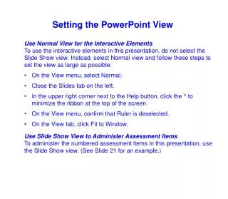
Save presentation, open in PowerPoint, and View “Notes Page” to see slide notes
Origo PhaseID System • No cell phones • No work delays due to lack of cellular coverage • Use on any voltage • Very portable (only 3 lbs) • Lowest cost solution available
A GPS timing signal is used to simultaneously measure phase at a reference location and at a field location. The phase attribute at the reference location is known. By comparing the reference and field phase measurements, the field phase attribute can be determined. Principal of Operation
Phase Measurement Comparisons • The reference phase base station can be connected to any convenient wall socket of any phase. • Each GPS second, the wall socket phase is measured and stored in a PC file. • When touched to any energized line, the field probe measures the unknown phase at the next GPS second and encodes it into a 9-digit sequence. • Base and field measurements can be compared at any convenient time and manner by simply entering the 9-digit sequence into the PC.
Handheld on Transmission Lines • 345KV • No extendo stick required. • Determine all 3 phases with a single measurement.
Handheld on Overhead Lines 69KV 12.5KV
Handheld in Cabinets 12.5KV Bushing 12.5KV test Point
Handheld in Substations 69KV Buss 12.5KV Buss
Convert a 20 Minute Extendo Stick Phasing Task on High Overhead Lines into a 20 Second Task using the Handheld 69KV
Lineman Field Probe Substation Buss 12.5KV Bushing
Lineman Field Probe Elbow Test Point Secondary Conductor
Non-Real-Time phase attribute determination. Write down the phase sequences and enter them into the base station later. Call your dispatcher, or any other utility personnel, and give them the 9-digit sequence. They will enter it into their PC and tell you the phase attribute. Real-Time phase attribute determination if Internet access available. Automatically records the phase sequence in a measurement file. Provides GPS location. Accepts user notes. Real-Time Satellite communication link available soon. Available in Manual or Datalogger Manual Version Datalogger Version
Tagging Reference Phase • Tagging reference phase is one of the most important concepts of phase identification. • Tagging reference phase simply refers to what phase attribute you wish to call each 3-phase conductor. • There is no universal “Phase A”. Phases A, B, and C are simply the phase attributes the utility wishes to tag or assign to each of the 3-phase conductors. • Once assigned, all conductors of the same phase are tagged according to this chosen tagging reference phase.
Batch Convert • All measurement sequences can be converted to phase attribute with a single click. • First, copy the base station daily reference file into the field PC data directory. • Next, click on the third icon to the right of the measurement sequence window (red-to-green icon). • This action converts all measurement sequences to phase attributes and changes all red dots to green dots.
PhaseID USA Customers (That we know of) Origo also has customers in Australia, Canada, India, Jamaica, New Zealand, and Taiwan.
Bottom Line When you are tasked with collecting thousands of attributes to phase identify your entire utility, no other system available is as fast and convenient as the Origo PhaseID System