Download
1 / 7
70 likes | 78 Views
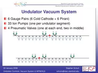
Service Vacuum System Design status. Sept 2009 B. Boussier ITER IO. SVS overview.

E N D
Service Vacuum SystemDesign status Sept 2009 B. Boussier ITER IO
SVS overview • SVS is designed to provide vacuum servicing to a large number of clients. Clients are mainly vulnerable components that require double containment with monitored interspaces. In addition, systems requiring vacuum to operate and temporary interspaces formed on a valve closure can also be services by the SVS in order to restrict the number of pumping system required. (Cryogenic isolation vacuum is not to be considered and pumped by a separate system, to avoid any chance of tritium contamination of the super-insulated lines). • Services includes: • Roughing • Backfilling • Purging/flushing • Pressure monitoring • High Vacuum pumping with dedicated local HV pumps if required. • About 1500 clients estimated so far • In addition, design should: • Be modular and flexible to the maximum extend • Allow leak detection/localization • Be tritium compatible
Old SVS • The old SVS design was based on a set of ring manifolds on L1 and under the NB cell : • Roughing ring manifold (DN300) – provide roughing to clients • Leak Detection manifold (DN300) – provide connection to VPR for leak detection • Guard vacuum manifold (DN300) – provide High vacuum to clients • Tracer and purge gas lines. • No routing was designed to port cells or distribution boxes (also not designed). • Routing to out of date location of the pumping room. • Cross contamination of systems unavoidable (tritium). • Design required many additional cryocoolers, pipes and compressors and is oversized… Also: SVS Requirements evolved… Routing above NB cell should already have disappeared Cryocoolers
Old SVS draft PFD Vacuum Pumping Room A Client RP Sorption Cryocoolers (x 6) SGVS S COVB SRS SLDS Leak Detection Condensation cryocoolers (x 6) C
New SVS • Based on same routing for main ring manifolds on L1 and under the NB cell, but assignation and sized modified (DN150): • Non tritium roughing – to rough Cryostat type clients (see tritium only in case of incident) • Tritium roughing –to rough Torus type clients (likely to see tritium from simple, single leaks) • Exhaust manifold – to route out purge gas from tritiated clients • Tracer gas, vent gas and purge gas lines • Vertical distribution uses every other pipe shaft to service distribution boxes in port cells. • Cross contamination is reduced to a maximum extend (Cryogenic insulation vacuum is provided buy a separate system (CGVS)) • Leak detection is provided through roughing manifold and MSLD in pumping room. In addition, local leak detector can be connected on boxes. • High vacuum is provided by local HV pumps (few clients) • Type 1 Diagnostics and ECRH serviced by SVS.
Side by side Comparison Old SVS New SVS New SVS New ring manifolds Old ring manifolds Old SVS New SVS