Download
1 / 33
390 likes | 836 Views
Geometric Dimensioning and Tolerancing. Unit 4 – Position Verification. Coordinate Measuring Machine (CMM). Typical ‘bridge’ CMM is composed of 3 axes. A touch probe indicates contact with a body. Typical precision measured in microns or micrometers (10 -6 m). CMM.

E N D
Geometric Dimensioning and Tolerancing Unit 4 – Position Verification
Coordinate Measuring Machine (CMM) • Typical ‘bridge’ CMM is composed of 3 axes. • A touch probe indicates contact with a body. • Typical precision measured in microns or micrometers (10-6 m)
Position Tolerance Verification • This unit covers some simple verification techniques for position tolerancing.
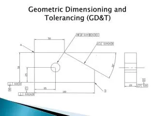
Position Tolerancing Verification 1 . 5 0 0 B . 7 5 0 2 . 5 0 0 . 7 5 8 ± . 0 0 5 . 7 5 0 A C . 0 1 0 A B C Size of hole is produced at .750 (MMC). 2X .005 = Ø.010 Tol Zone X² + Y² = Z X² + Y² = Diameter Tol Zone 2 .005 .004 1.504 Actual .003 M 2.503 Actual X² + Y² = Z² - Pythagorean Theorem Actual Manufactured Part 1.500 Let us check this part to see if the hole location is within tolerance. 2.500 3.6
Position Tolerancing Verification 1 . 5 0 0 B . 7 5 0 2 . 5 0 0 . 7 5 8 ± . 0 0 5 . 7 5 0 A C . 0 1 0 A B C .005 .004 1.504 Actual M 2.503 Actual Since the hole is produced at MMC (.750), it is allowed .010 position tolerance. The actual calculated position of the hole falls within the .010 zone. 2X .005 = Ø.010 Tol Zone Actual Manufactured Part .003 1.500 2.500 3.6
Position Tolerancing Verification 1 . 5 0 0 B . 7 5 0 2 . 5 0 0 . 7 5 8 ± . 0 0 5 . 7 5 0 A C . 0 1 0 A B C Size of hole is produced at .755. .005 1.505 Actual .006 M 2.506 Actual Let us try another example, this time the hole is produced at .755. Is the location good or bad? Actual Manufactured Part 1.500 Let us check this part to see if the hole location is within tolerance. 2.500 3.6
Position Tolerancing Verification 1 . 5 0 0 B . 7 5 0 2 . 5 0 0 . 7 5 8 ± . 0 0 5 . 7 5 0 A C . 0 1 0 A B C .005 1.505 Actual .006 M 2.506 Actual If the hole is produced at .755, it is allowed a position tolerance of .015. The calculations show the hole is produced within a .0156 zone, so the hole location is out by .0006. 2X .0078 = Ø.0156 Tol Zone .0078 1.500 The above part may be repaired by opening the size of the hole by .0006. 2.500 3.6
Class Exercise Position Verification At MMC- Inch As drawn Produced part 4.5
Class Exercise Position Verification At MMC- Inch As drawn MMC =Smallest Hole Produced part MMC = Smallest Hole .371 4.5
Class Exercise Position Verification At MMC- Inch As drawn Actual Size of Hole Produced part Actual Size of Hole .376 .371 4.5
Class Exercise Position Verification At MMC- Inch As drawn .005 Position Plus .005 Departure from MMC .010 Produced part Position + Departure from MMC = .010 .376 .010 .371 4.5
Class Exercise Position Verification At MMC- Inch As drawn Produced part X Deviation .376 .010 .371 -.004 4.5
Class Exercise Position Verification At MMC- Inch As drawn Produced part Y Deviation Y Deviation .376 .010 .371 +.002 -.004 4.5
Class Exercise Position Verification At MMC- Inch As drawn Produced part From Chart .376 .010 .371 +.002 -.004 .0089 4.5
Class Exercise Position Verification At MMC- Inch As drawn Produced part From Chart .376 .010 .371 +.002 -.004 .0089 X 4.5
Class Exercise Position Verification At MMC- Inch As drawn Produced part .376 .010 .371 +.002 -.004 .0089 X .371 4.5
Class Exercise Position Verification At MMC- Inch As drawn Produced part .376 .010 .371 +.002 -.004 .0089 X .379 .371 4.5
Class Exercise Position Verification At MMC- Inch As drawn Produced part .376 .010 .371 +.002 -.004 .0089 X .379 .013 .371 4.5
Class Exercise Position Verification At MMC- Inch As drawn Produced part .376 .010 .371 +.002 -.004 .0089 X .379 .013 .371 +.004 4.5
Class Exercise Position Verification At MMC- Inch As drawn Produced part .376 .010 .371 +.002 -.004 .0089 X .379 .013 .371 +.004 +.005 4.5
Class Exercise Position Verification At MMC- Inch As drawn Produced part .376 .010 .371 +.002 -.004 .0089 X .379 .013 .371 +.004 .0128 +.005 4.5
Class Exercise Position Verification At MMC- Inch As drawn Produced part .376 .010 .371 +.002 -.004 .0089 X .379 X .013 .371 +.004 .0128 +.005 4.5
POSITION Hole Verification at MMC 4.3
Workshop Exercise 4.6 - Inch 4.14
Workshop Exercise 4.6 - Inch 4.14