Download
1 / 65
820 likes | 1.79k Views
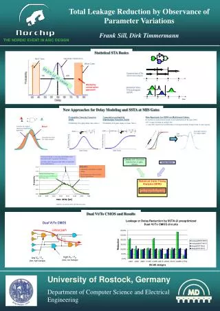
Chapter 2: Static Timing Analysis. Massoud Pedram Dept. of EE University of Southern California . Outline. Background Gate Delay Analysis K-factor Approximation Effective Capacitance Approach Wire-Load Delay Analysis Interconnect Modeling Transmission Line Equations Elmore Delay

E N D
Chapter 2: Static Timing Analysis Massoud Pedram Dept. of EE University of Southern California
Outline • Background • Gate Delay Analysis • K-factor Approximation • Effective Capacitance Approach • Wire-Load Delay Analysis • Interconnect Modeling • Transmission Line Equations • Elmore Delay • S2P Approach • Appendices
Motivation • Does the design meet a given timing requirement?!! • How fast can I run the design?!!!
What’s the problem? Delays on signals due to wires no longer negligible Modern designs must meet tight timing specifications Layout tools must guarantee these timing specifications How can we address the problem during physical design? By ignoring it, mostly Implicitly, qualitatively We try to make layout area small and wires short We rely on cell libraries with many cell drivers strengths We employ accurate, yet efficient, timing analysis tools We develop timing-aware design optimization methodologies, flows and tools The Problem and Its “Solution”
Background • Mid 80 Scenario • Most of the input to output delay of the logic is due to gate delay 15% delay 85% delay • Mid 90 Scenario • Half of input to output delay of the logic is due to wire delay 50% delay 50% delay 80% delay • Today’s Scenario • Most of input to output delay of the logic is due to wire delay 20% delay
Guidelines to Meet Timing • With higher chip speeds and densities on the horizon, getting quick and accurate feedback on signal delays during design has become a critical issue. With ever-increasing time-to-market pressures, designers must be able to: • Analyze timing early and often throughout the design process by using high-fidelity and efficient timing analysis tools • Decrease the number of independent optimization steps in the design cycle (unification-based approach) • Eliminate the time spent debugging erroneous timing results • Have the capability to make design changes that can be re-timed quickly without having to entirely re-run static timing analysis from scratch in a separate environment • Ensure that all intermediate timing analysis results correlate well with the final timing results • Verify the delay and timing of the finished product
Input-to-Output Propagation Delay • The circuit delay in VLSI circuits consists of two components: • The 50% propagation delay of the driving gates (known as the gate delay) • The delay of electrical signals through the wires (known as the interconnect delay)
Gate Delay and Output Transition Time • The gate delay and the output transition time are functions of both input slew and the output load
Output Transition Time Vout Vin W W p p 90% Vin Vout C C t M M out Cdiff Cload W W t t t 10% n n in in out Time Cout Gate Delay Definitions
Output Transition time (s) Output Transition time (s) 10-14 CLoad (F) 10-10 Input Transition Time (s) Output Transition Time • Output transition time as a function of input transition time and output load
ASIC Cell Delay Model • Three approaches for gate propagation delay computation are based on: • Delay look-up tables • K-factor approximation • Use of a Thevenin equivalent circuit composed of a voltage source and a resistance in series with the gate load. • Although the first approach is currently in wide use especially in the ASIC design flow, the third approach promises to be more accurate when the load is not purely capacitive. This is because it directly captures the interaction between the load and the gate/cell structure. The resistance value in the Thevenin model is strongly dependent on the input slew and output load and requires output voltage fitting.
115pS Table Look-Up Method • What is the delay when Cloadis 505f F and Tin is 90pS?
Output Transition time (s) Output Transition time (s) 10-14 CLoad (F) Input Transition Time (s) 10-10 K-factor Approximation • According to above, we can write the output transition time as a function of input transition time and output load as a polynomial functions with curve fitting. As an example, consider: • A similar equation (with different coefficients, of course, gives the gate delay
D2 D1 D3 D4 Two Dimensional Table
Second-order RC-p Model • Using Taylor Expansion around s = 0
Second-order RC-p Model (Cont’d) • This equation requires creation of a four-dimensional table to achieve high accuracy • This is however costly in terms of memory space and computational requirements
Effective Capacitance Approach • The “Effective Capacitance” approach attempts to find a single capacitance value that can be replaced instead of the RC-p load such that both circuits behave similarly during transition
Rp 0 k = 1 Rp ∞ k = 0 Effective Capacitance (Cont’d) 0<k<1 • Because of the shielding effect of the interconnect resistance , the driver will only “see” a portion of the far-end capacitance C2
Macy’s Approach • Assumption: If two circuits have the same loads and output transition times, then their effective capacitances are the same. In other words, the effective capacitance is only a function of the output transition time and the load
Macy’s Approach (Cont’d) Normalized Effective Capacitance Function
Macy’s Iterative Solution • Compute a from C1 and C2 • Choose an initial value for Ceff • Compute Tout for the given Ceff and Tin • Compute b • Compute g from a and b • Find new Ceff • Go to step 3 until Ceffconverges
Eff_Cap Equation • See expressions for w, a, and f in the paper by Abbaspour/Pedram • This is a non-Linear algebraic equation, which must be solved by iteration • A good initial value for Ceff can speed up the procedure to find the answer
(C1=15fF, C2=20fF) Ceff (fF) Ceff (fF) Rp (K) Rp (K) (b) driver size=100l,TR= 200pS (a) driver size=500l,TR=100pS Initial Guess
USC’s Iterative Solution 1. Start with the initial guess for Ceff 2. Obtain t0-50% based on values of Ceff and TR 3. Obtain Rd based on values of Ceff and TR 4. Compute a new value of Ceff from the Eff_Cap equation 5. Record the previous value of t0-50% . Find current t0-50% based on the new Ceff and given TR 6. Compare the previous and current values of t0-50% from step 5 7. If not within acceptable tolerance, then return to step 3 until t0-50% converges 8. Report t50%propagation delay and t0-80% from the table
Interconnect Analysis • So far, we have only discussed the gate delay • How do we calculate the interconnect delay? • Precise delay calculation needs transmission line analysis
Transmission Line Equations • Drop across R and L is : • Current through C and G is : • The resulting equation is as follows: Infinitesimal Model of a Transmission Line
Impedance of an Infinite Line • An infinite length of RLCG transmission line has an impedance: • Driving a line terminated in Z0 is the same as driving Z0 • In general, Z0is complex and frequency dependent. • For LC lines, Z0is real and independent of frequency and is given by:
R C L C R L C Simple Transmission Line Models • Generally speaking, G=0 • Ideal • Lumped Wires (purely C, R or L) • Pure C section: most short signal lines and short sections of low-impedance transmission lines • Pure R section: on-chip power supply wires • Pure L section: off-chip power supply wires and short sections of high-impedance transmission lines • RC Transmission Lines • Long on-chip wires; L=0; Diffusion Equation • Lossless LC Transmission Lines • Most off-chip wires; R=0; Wave equation • Reflections and the Telegrapher’s equation • Lossy RLC Transmission Lines • Wave attenuation and DC attenuation • Combined traveling wave and diffusive response • The skin effect
Low-Frequency RC Line, 24AWG Twisted Pair • R=0.08 W/m, C=40 pF/m and L=400 nH/m • f0=R/(2pL)=33Khz • Below f0, Line is RC with • Above f0, Line is LC with
Lossy RC Transmission Lines • Most real lines dissipates power. The loss is due to resistance of the conductor and conductance of the insulators. • RC lines are an extreme case: • R >> wL • Propagation is governed by the diffusion equation: • Typical of on-chip wires: • R=150k/m • L=600nH/m • f=40Ghz
Delay: Rise Time: Step Response of a Lossy RC Line • Signal is dispersed as it propagates down the line: • R increases with length, d • C increases with length, d • Delay and rise time are proportional to RC and then increases with d2 • In many cases the degradation of the rise time caused by the diffusive nature of RC lines as much a problem as the delay
Lossless LC lines • If R and G are negligible, then line is lossless (i.e., no heat generation and the line is governed by the wave equation) • Waves propagate in both directions without any loss • Line is described by its impedance and velocity
Reflections and the Telegrapher’s Equation in a Lossless LC Line • When a traveling wave reaches the end of the line with impedance Z0 terminated in an impedance ZT, then it is reflected • Telegrapher’s equation relates the magnitude and phase of the incident wave to those of the reflected wave as follows: • Kr = Ir/Ii = Vr/Vi = (ZT-Z0)/(ZT+Z0) • Some common terminations • Open-circuit • Short-circuit • Matched • Source termination and multiple reflections
Lossy RLC Transmission Lines • LC lines with resistance in conductors and conductance in dielectrics: • Combined traveling wave and diffusive response • The amplitude of the traveling wave is reduced exponentially with distance along the line • For a line with matched termination, the steady-state response is attenuated by a DC amount proportional to the inverse of the length of the line • Disperses the signal • Fast rise due to traveling wave behavior • Slow tail due to diffusive relaxation • Resistance (due to the skin effect) and conductance (due to dielectric absorption) are in fact dependent on the frequency. Both effects result in increased attenuation at higher frequencies Skin effect: High frequency current density falls off exponentially within depth into conductor
R vs(t) v1(t) C Lumped RC Model for On-chip Wires • Impulse response and Step Response of a lumped RC circuit
RC Model (cont’d) • Transfer Function of RC Networks
RC Model: Important Notes Impulse response:
1v V(t) R C Elmore Delay Time Constant=RC • What is the time constant for more complex circuits?
Elmore Delay (Cont’d) • Resistance-oriented Formula: i on path Tdelay,4=R1(C1+C2+C3+C4+C5)+R2(C2+C4+C5)+R4C4
Elmore Delay (Cont’d) • The Elmore delay is negative of the first moment of the impulse response, -m1 • If the impulse response is symmetric, then –m1 = tmedian • However, in RC network, tmedian < -m1 • Thus, the Elmore delay gives an upper bound of the delay