Download
1 / 17
170 likes | 253 Views
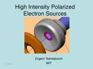
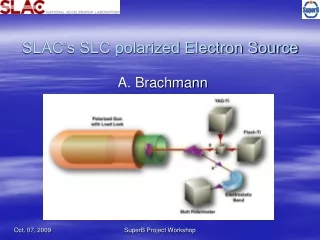
The SLAC Polarized Electron Source. J. Clendenin, A. Brachmann, T. Galetto, D.-A. Luh, T. Maruyama, J. Sodja, J. Turner Stanford Linear Accelerator Center, Menlo Park, CA 94025.

E N D
The SLAC Polarized Electron Source J. Clendenin, A. Brachmann, T. Galetto, D.-A. Luh, T. Maruyama, J. Sodja, J. Turner Stanford Linear Accelerator Center, Menlo Park, CA 94025 The SLAC PES, developed in the early 1990s for the SLC, has been in continuous use since 1992, during which time it has undergone numerous upgrades. The upgrades include improved cathodes with their matching laser systems, modified activation techniques and better diagnostics. The source itself and its performance with these upgrades will be described with special attention given to recent high-intensity long-pulse operation for the E-158 fixed-target parity-violating experiment.
Characteristics Cathode diameter 20 mm (emitting area) Cathode holder Mo puck with Ta cup Cathode operating temperature 0 ºC Electrodes: 317L stainless steel with low carbon content, low inclusion density High voltage insulator 39.5-cm long by 19.0-cm ID fluted alumina Design bias voltage -150 kV Operating bias voltage -120 kV Dark current at nominal voltage 30 nA typical Vacuum pumping 120 lps DI and 200 lps NEG pumps Vacuum ~10-11 Torr dominated by H2 Ti:sapphire laser systems: Nd:YLF pumped 2 ns pulse for PEP II, FFTB Flashlamp pumped 100-400 ns pulse for ESA polarized beam Brachmann/Session 8
Configuration History First gun operational Early 1992 Load-lock added 1993 Cathode Pe (%) Polarization Experiment Bulk GaAs 25 1992 SLC Bulk AlGaAs 35 1992 E142 300-nm strained GaAs 65 1993 SLC 100-nm strained GaAs 80 1993 E143 1994-98 SLC 1995 E154 1996 E155 1999 E155X Gradient doped strained GaAs 80 2001-presentt
Improvements Before 1995 4-guns, each assembled under carefully controlled conditions in Class 1000 clean room Addition of preparation chamber/ load-lock All activativations are done in preparation chamber with gun vacuum isolated Effusion cell SAES channel cesiators Re-cesiations under computer control after operator initiation 14 20 mm diameter photocathode crystal QE monitoring
1995 to present Emitter tube brazed joint SF6 SF6/dry air dry air in shroud Gradient doped cathode – Maruyama/Session 1 Partial success Vacuum transfer of activated cathode No success Rinsing with ultrapure water to remove dust during assembly of gun components Untried Glove box
Emitter Tube Brazed Joint Emitter tube transports photocathode puck to and from the gun. Interior of tube (atmospheric pressure) used for heating and cooling the cathode. Puck end heated to ~800 C. Tube made of Mo, brazed to Kovar that is welded to seamless stainless steel 304L tube. Kovar Ni-plated prior to brazing to provide chemically clean surface. [R. Kirby and G. Collet] Temperature response modeled using ANSYS 5.1 to determine optimum length of Mo to keep temperature of at brazed joint <250 C. [G. Mulhollan and G. Kraft] Tested 70 cycles under computer control: ramp to 800 C, hold for 1 h, ramp down.
Operating Experience • The SLAC PES has been the source of ~80% of electron beams for the SLAC linac since 1992, accumulating nearly 40,000 hours of operation with availability >>95%. • Except for 1992, when there was no load-lock, the pattern has been the same, independent of the type of cathode used (but all having GaAs as the active surface): • After initial activation (by heat-cleaning to ~600 C and then co-depositing Cs/F), the cathode is inserted into the gun. • Neither the HV nor the presence of the electron beam are observed to have any effect on the QE. • When the QE decreases to the point where the required current can no longer be obtained (because of limited laser energy and/or because of the surface charge limit), the cathode is re-cesiated in the gun with the bias voltage low (~1 kV). This typically occurs ever 3-5 days and takes ~20 minutes (dominated time-wise by cycling the HV). It is estimated about 0.5 ML Cs is added per re-cesiation. No F (NF3) is added. The re-cesiation completely restores the original QE. • The above re-cesiation process can be repeated up to at least 50 times over the period of a year limited only by operational considerations to preemptively change the cathode during the scheduled accelerator major maintenance times. During the operational period there is no change in the QE lifetime.
E158* NLC Intensity/macropulse 6x10¹¹ 27x1011 Rep. rate 120 Hertz 120 Hertz Intensity jitter <0.5% 0.5% Energy 45 GeV 250 GeV Energy jitter 0.02% 0.3% Pulse train 270 ns 267 ns Microbunch spacing 0.35 ns 1.4 ns e- polarization ~80% 80% Transverse jitter 5% of spotsize 22% sx, 50% sy Energy spread 0.15% 0.25% Parameters Achieved for E158 and Needed for NLC *Mastromarino/Session 7
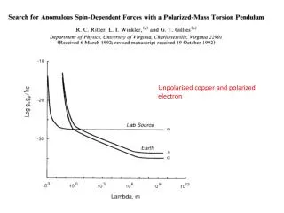
Top curve is the charge in a 100-ns long train using the E-158 high-surface-doped (5×10¹⁹/cm3) strained GaAs cathode plotted versus laser intensity. Lower curve is the charge in a 350-ns train using a standard SLC strained GaAs with 5×10¹⁸/cm3 uniform doping.
Ongoing and Future R&D Low temperature cathode cleaning techniques – Luh/Session 5 Superlattice cathodes – also Luh Cathode non-cleaning? [Poelker (JLAB)] Ion-implanted electrode material? [Sinclair et al., PAC01]
Published Papers on the SLAC PES as a System J.L. Turner et al., “A High-Intensity Highly-Polarized Electron Beam for High-Energy Physics,” presented at the 2002 European Particle Accelerator Conference, June 3-7, 2002, Paris, FR. G. Mulhollan et al., “Reflections on the SLAC Polarized Electron Source,” in Low Energy Polarized Electron Workshop, LE98 Proceedings, eds. Y.A. Mamaev, S.A. Starovoitov, T.V. Vorobyeva, A.N. Ambrazhei, SPES-Lab-Publishing, St. Petersburgh, Russia (1998), p. 102. J.E. Clendenin et al., The SLAC Polarized Electron Source,” in Polarized Gas Targets and Polarized Beams, eds. R.J. Holt, M.A. Miller, AIP Conf. Proc. 421 (1998), p. 250. H. Tang et al., “The SLAC Polarized Electron Source,” in Polarized Beams and Polarized Gas Targets, eds. H.P. gen. Schieck, L. Sydow, World Scientific (1996), p. 301. R. Alley et al., “The Stanford linear accelerator polarized electron source,” Nucl. Instrum. and Meth. A 365 (1995) 1. D. Schultz et al., “The Polarized Electron Source of the Stanford Linear Accelerator Center,” LINAC94. D. Schultz et al., “The High Peak Current Polarized Electron Source of the Stanford Linear Collider,” Nucl. Instrum. and Meth. A 340 (1994) 127. J.E. Clendenin et al., “Performance of the SLC Polarized Electron Source with High Polarization,” Proc. of the 1993 Part. Acc. Conf., PAC93, p. 2973. A.D. Yeremian et al., “Performance of the SLC Polarized Electron Source and Injector with the SLAC 3-km Linac Configured for Fixed Target Experiments,” Proc. of the 1993 Part. Acc. Conf., PAC93, p. 3027. D. Schultz, “Polarized Source Performance in 1992 for SLC-SLD,” in Frontiers of High Energy Spin Physics, eds. T. Hasegawa, N. Horikawa, A. Masaike, S. Sawada, Universal Academy Press (1993), p. 833. D. Schultz, “The Polarized Electron Gun for the SLC,” EPAC92, v. 2, p. 1029.