Download
1 / 11
140 likes | 926 Views
Clocked Synchronous State-Machines. Such machines have the characteristics: Sequential circuits designed using flip-flops. All flip-flops use a common clock (clocked synchronous).

E N D
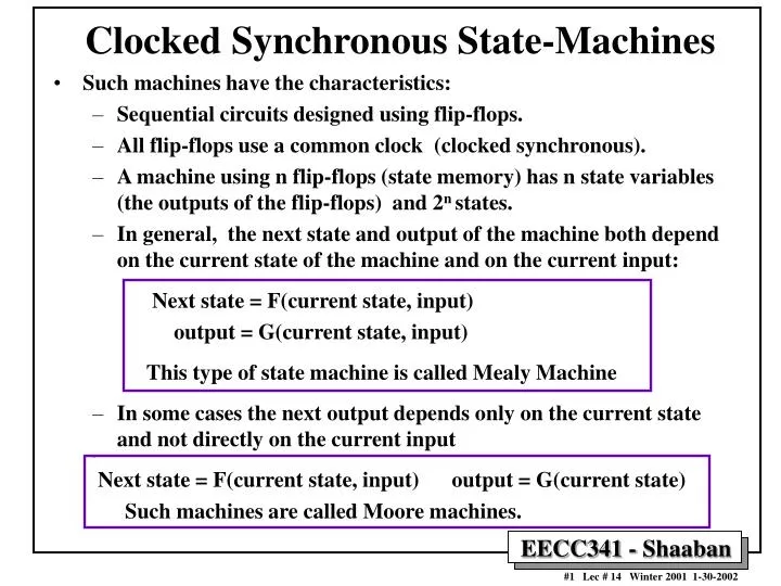
Clocked Synchronous State-Machines • Such machines have the characteristics: • Sequential circuits designed using flip-flops. • All flip-flops use a common clock (clocked synchronous). • A machine using n flip-flops (state memory) has n state variables (the outputs of the flip-flops) and 2n states. • In general, the next state and output of the machine both depend on the current state of the machine and on the current input: Next state = F(current state, input) output = G(current state, input) This type of state machine is called Mealy Machine • In some cases the next output depends only on the current state and not directly on the current input Next state = F(current state, input) output = G(current state) Such machines are called Moore machines.
Clocked Synchronous State-Machine Model (Mealy machine) Next-state Logic F State Memory clock Output Logic G inputs excitation outputs current state State memory: Usually edge-triggered D or JK flip-flops clock Moore Machine
Latch/Flip-Flop Characteristic Equations • The next output of a flip flop (or next state) can be obtained from the function table of each type of flip-flop. • This latch/flip-flop next output behavior is expressed in as a characteristic function which gives the next state in terms of the current state and output: Q* = f (Q , inputs) (Q* is the next state of Q). • Vary important in state machine analysis and design.
Characteristic Equations D latch or flip-flop present next input state state D Q(t) Q* ________________________________________ 0 0 0 0 1 0 1 0 1 1 1 1 ________________________________________ Characteristic Equation: Q* = D S-R latch S R Q(t) Q* ____________________________________________________ 0 0 0 0 0 0 1 1 0 1 X 0 1 0 X 1 1 1 X X __________________________________________________ Characteristic Equation: Q* = S + R’. Q
Characteristic Equations J-K flip-flop J K Q Q* _______________________________________________________ 0 0 0 0 0 0 1 1 = hold 0 1 0 0 0 1 1 0 = reset 1 0 0 1 1 0 1 1 = set 1 1 0 1 1 1 1 0 = flip ______________________________________________________ Characteristic Equation: Q* = J . Q’ + K’. Q T flip-flop with enable T Q Q* ________________________________________ 0 0 0 0 1 1 1 0 1 1 1 0 ________________________________________ Characteristic Equation: Q* = T. Q’ + T’ .Q
Latch/Flip-Flop Characteristic Equations Device Characteristic Equations S-R latch Q* = S+R’.Q D latch Q* = D Edge-triggered D flip-flop Q* = D Master/Slave S-R flip-flop Q* = S+R’.Q Master/Slave J-K flip flop Q* = J.Q’ + K’.Q Edge Triggered J-K flip-flop Q* = J.Q’ + K’.Q T flip-flop Q* = Q’ T flip-flop with enable Q* = EN.Q’ + EN’.Q
Clocked Synchronous State-machine Analysis Given the circuit diagram of a state machine: • Analyze the combinational logic to determine flip-flop input (excitation) equations: Di = Fi (Q, inputs) • The input to each flip-flop is based upon current state and circuit inputs. • Substitute excitation equations into flip-flop characteristic equations, giving transition equations: Qi* = Hi( Di ) • From the circuit, find output equations: Z = G (Q, inputs) • The outputs are based upon the current state and possibly the inputs. • Construct a state transition/output table from the transition and output equations: • Similar to truth table. • Present state on the left side. • Outputs and next state for each input value on the right side. • Provide meaningful names for the states in state table, if possible. • Draw the state diagram which is the graphical representation of state table.
State Diagram Basic Format: State Output Format: Arc = input X Node = state/output Q Moore 0 1 Input A B 0 1 Mealy 0, 1 1 / 1 0/0 A B 0 / 1, 1 / 0 Format: Arc = input X / mealy output Y Node = state
x Q1 Q Q D D Q1' Q' Q' Q0 Q0' CP y State Machine Analysis Example Analyze the state machine: 1 Input (or excitation) equations: D0 = Q1’. X D1 = Q1 . x + Q0 . x 2 Characteristic equations: Q0* = D0 Q1* = D1 Find State equations: Q0* = Q1’. x Q1* = Q1 . x + Q0 . x 3 Output equation: y = (Q0 + Q1) . x' • This is a Mealy Machine since output = G(current state, input)
x Q1 Q0 0 1 0 0 00,0 01,0 0 1 00,1 11,0 1 0 00,1 10,0 1 1 00,1 10,0 Q1* Q0* , y State Machine Analysis Example • From the state equations and output equation, construct the state transition/output table: Input State equations: Q0* = Q1’. x Q1* = Q1 . x + Q0 . x Output equation: y = (Q0 + Q1) . x' Current State Output for current state when x =1 Next State when x =0 Next State when x =1 Output for current state when x =0
x Q1 Q0 0 1 0 0 00,0 01,0 0 1 00,1 11,0 1 0 00,1 10,0 1 1 00,1 10,0 0/0 1/0 0/1 10 00 1/0 0/1 0/1 1/0 01 1/0 11 Q1* Q0* , y State Machine Analysis Example • Draw the state diagram of the state machine. state transition/output table state diagram Arc = input x / output y Node = state