Download
1 / 25
250 likes | 348 Views
Analysis on TEC Expressline II modules. Two different topics: Strip defects (3 modules) Global IV (2 modules). Good & Bad news: Add. Pinholes No problem due to bonding!. 3 (+2 later) additional pinholes were reported by Aachen wrt QTC in Vienna!

E N D
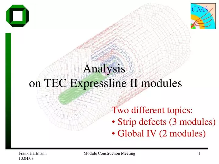
Analysis on TEC Expressline II modules • Two different topics: • Strip defects (3 modules) • Global IV (2 modules) Module Construction Meeting
Good & Bad news: Add. PinholesNo problem due to bonding! • 3 (+2 later) additional pinholes were reported by Aachen wrt QTC in Vienna! • Investigated in KA with QTC and DAQ! • 3 pinholes were related to deep scratches! • 1 burn!?! • 1 misstag Reported add. pinhole! Module 644 strip 358 Module Construction Meeting
Module 642 strip 329,330,331 Scratches:sensor defects (mod 642) Strip 328: leaky Strip 330: pinhole Module Construction Meeting 1 Scratch from strip 327 to 331 produced 2 different defects!
Module 642 -- strip scan on module Coupling capacitances: all in specs Overflow @ strip 330 pinhole Rpoly: all in specs • NB. Strip 1 reported as a pinhole: • is dubious in the DAQ, but not clearly identifiable as pinhole! • shows no damage! • is no pinhole according to the Idiel measurement at QTC! Module Construction Meeting
Mod 643add pinholes betweenDEC02 to JAN03 Strip 221 This happened somewhere after the first module tests! Strip 511 More on this one later Module Construction Meeting
IV Module Construction Meeting
IV problems reported by Aachen • For a “good” IV evaluation (with a dubious first one) one should take at least fast 2-3 IV ramps OR ramp up – wait – IV during ramp down. • The stepping of 100V done in Aachen was not suited for full modules (there’s a chance for higher values) • Module 642 is fine (more on this) • (mod 503 fine up to ~500V, then fast increase to ~10µA to be investigated). • Module 643: early breakdown at 100-200V (more on this one) Module Construction Meeting
Module 642High IV + early soft breakdown 4µA 2µA Slight but non-critical increase in IV! Compare to the 40µA limit! Initial current decrease with time! Known IV behaviour of sensors! Module Construction Meeting
Mod 643 High IV + early soft breakdown Module Construction Meeting
IV reported by AachenMod 643 First IV is fine! ´What happened? Module Construction Meeting
Module 643 (history) • Full module shows high global IV • Optical inspection showed possible candidates for the high IV, • NO candidates on the edges • NO; on the visible part of the backplane. • Yes; on strip level • Yes; on bias / guard region • Strip scan (leakage current) on W6A (on module) show nominal currents (W6B not accessible) Removal of bonds (for further deep investigation on indiv. Sensors.) Module Construction Meeting
Module 643 history(cont.) • IV on W6A is ok, IV on W6B shows early breakdown as full module! • Cleaning improved the current but did not solve the problem: • A) Isoprop, B) isoprob plus tissue, (C) ultrasonic bath) • Strip scans (leakage current) on both sensors show nominal currents! IV problem is NOT located in the strip region! • Remaining defect location: Backside, Guard-, Bias, n++ -region! • Removal of W6B with a scalpel no further increase in IV! • NO visible breaks on the backplane (add. inspection on the edges) Remaining defect location: Guard-, Bias, n++ -region! Module Construction Meeting
IV on module 643 • Closer investigation on W6B SENSOR Starting assumption: • indiv. strip failure as seen on sensors • backplane cracks/chips • guard scratches • bias scratches • contact of guard and n++ Module Construction Meeting
Module 643Strip leakage current Sum of individual currents is way below the total current! (Nominal values) Individual strip currents are as expected for HPK (very low)! Other strip parameters checked for are in specs! Module Construction Meeting
Backside – not critical Non critical scratches on the backside compare with scratch tests on the backside and scalpel scratches (during removal), which did not increase the current. Exististing scratch Scalpel wounds during removal Non-destructive! Scratches on the back are probably not critical. Non-destructive test on mini sensor Module Construction Meeting
Scratch on n++,guard and bias Scratch exists before end of bonding! Possible defect candidate: Metal overhang defect! Module Construction Meeting
Scratch test on bias & guard (minisensor) Artifical: Metaloverhang defect Module Construction Meeting
Preliminary field simulations (with ISE TCAD) Module Construction Meeting
Module 643 (strange) On n++ On strip Possible defect candidate: Short: n++ and guard Most probable candidate! Module Construction Meeting
IV with “shorts” in the outer sensor areas Module Construction Meeting
Repair of module 643 Repair is feasible but not applicable as standard procedure! Not fully bonded yet. Module Construction Meeting
GENERAL: Global IV and Individual strip IV (sensors) Scratches on QTC level! (e.g. from company or artificial) Total current Single strip current x3 x70 Module Construction Meeting
General comment on scratches!During Assymbly, Bonding, Testing • DO NOT SCRATCH SENSORS / DO NOT POLLUTE THEM!! • especially not the guardring ! • especially not the strips ! • do not break the edges ! • do not break any border line ! • SMALL SUPERFICIAL scratches are enough to change sensor/module characteristics! • Local & global HIGH increase of current • Add shorts, breaks, pinholes! Contrary to older experiments: The high voltage sensor design is good but vulnerable to scratches! Pollution: Use Facemasks everywhere working with open sensors/modules! Module Construction Meeting
W5 prototype production (manual) Module Construction Meeting
IV on W5 Module Construction Meeting