Download
1 / 39
390 likes | 602 Views
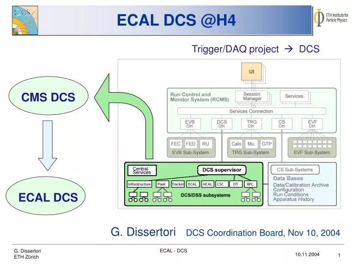
CMS DCS. ECAL DCS. ECAL DCS @H4. Trigger/DAQ project DCS. Status report. G. Dissertori DCS Coordination Board, Nov 10, 2004. Outline. Overview Precision Temperature Monitoring (PTM) Humidity Measurement (HM) ECAL Safety System (ESS) PVSS Monitoring (and related issues)

E N D
CMS DCS ECAL DCS ECAL DCS @H4 Trigger/DAQ project DCS Status report G. Dissertori DCS Coordination Board, Nov 10, 2004 ECAL - DCS
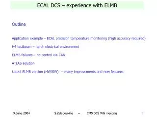
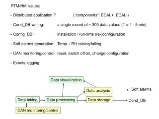
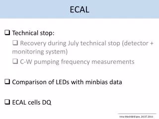
Outline • Overview • Precision Temperature Monitoring (PTM) • Humidity Measurement (HM) • ECAL Safety System (ESS) • PVSS Monitoring (and related issues) • Note : For details on the PTM/HM and ESS hardware (sensors, readout) I refer to the DCS ESR, May 04! ECAL - DCS
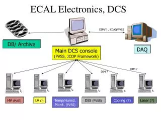
prec. temp. sensor ESS temp. sensor + WLD humidity sensor Monitoring interlock Monitoring Safety, PLC cooling, faults Overview Laser system cooling Data Bases ECAL module Offline, DAQ crystal PCBs for VFE and FE PVSS LV, HV ECAL - DCS
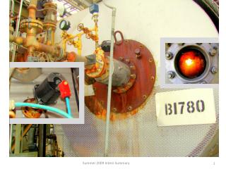
SM10 ECAL - DCS
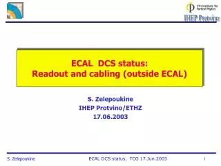
PTM Precision Temperature Monitoring - PTM S. Zelepoukine, IHEP Protvino and ETHZ ECAL - DCS
PTM • Requirements: • very high precision temp. monitoring : check stability of water cooling system, to stay within 0.02 - 0.05 deg C. • no hardwired feedback to cooling • relative precision : 0.01 deg C • one sensor/module on thermal screen and grid • main water IN, main water OUT ECAL - DCS
PTM : Sensor location Sensor probes location inside SM: M1 M2 M3 M4 Patch panel Grid Probes of type 1 (N = 4 + 4) Probes of type 2 (N = 2) Patch panel Thermal screen Number of probes (per SM): 4 + 4 + 2 = 10 Each probe has its own signal cable – twisted pair ECAL - DCS
PTM : Readout - Layout Network access Counting room UXC55 balcony: ECAL PC / PVSS Cur.src CANbus cables DC Power supplies ELMB 20x2 STP cables Galvanic isolation ~ 500 sensors (NTC thermistor Betatherm; 100K @ 25C; indiv.calibrated; better than 0.01C rel.accuracy) Readout electronics: ELMB based; ELMB reads voltages and converts to digital data, then sends data via CANbus. DC-DC converters Monitoring application: PVSS based; data storage/archiving, visualization/trending, warnings/alarms. ECAL - DCS
PTM @ H4 ECAL - DCS
Recent Results • First results from SM10 at H4: • Sensors, sensor probes, read-out practically final • Reading 4 sensors on grid, 3 sensors on thermal screen, and Water IN/OUT • One sensor lost, most likely due to bad intermediate connection inside SM before PP • Since about one week : installed 2 sensors on backplate • Above M1 and M4 ECAL - DCS
Zoom Cooling Stability ECAL - DCS
Grid M4 0.01C M3, M2 M1 Zoom : Thermal screen M4, M3 M1 0.01C Water - IN 0.01C Cooling stability = 0.01C (incl. day/night oscillations) ECAL - DCS
Grid Div = 0.01C Just to show uncompressed (in time) data… Thermal screen Div = 0.01C Water - IN Div = 0.01C Ambient Div = 1.0C 10 min ECAL - DCS
M1 M2 M3 M4 28.5 30.6 28.2 25.7 M2 M1, M3 M4 Inside the electronics compartment From ESS, see later… ECAL - DCS
Conclusions on PTM • Cooling stability: • Achieved 0.01 C in the long-term, including day/night variations • Have a monitoring application, Serguei is working on a more “final” version… • Temperatures on outer surfaces • Recent measurements performed by Serguei • Is heating towards outside (or inside, depending on orientation) an issue? For other detectors? For other SMs ? • As next step, Serguei will move external sensors to lateral surfaces… • Hardware • Resolve issue of immersion probes • Intermediate connections will not be there any more ECAL - DCS
HM Humidity Monitoring - HM S. Zelepoukine, IHEP Protvino and ETHZ ECAL - DCS
Requirements • For HM we want to • Measure humidity level inside modules, precision about 5% • Sensors • One per module • UPS600 from Ohmic Instruments, resistive type, cheap • Transducers also from Ohmic Instr, • Readout • Same principles as for PTM : ELMB + Canbus to PC ECAL - DCS
RH cable shield grounded to SM10 M1, M3, M4 M2 (conn.broken) RH – inside SM10 RH -- ambient Amb1/2 (SM10) Amb_3 (DCS rack) water out Water temperatures water in Ambient temperatures ECAL - DCS
HM : Conclusions • A complete SM has been equipped with RH sensors and readout (SM10 in H4 testbeam) • Non-calibrated sensors/transmitters were used for SM10 • nevertheless acceptable channel to channel variations (2-4 %RH). • The RH readout chain “sensor-transmitter-ADC” is rather sensitive to the grounding of the HM signal cable shield: changing the grounding point can result in an offset for the measured RH value equal to about 10% RH • A detailed lab study is planned for investigating HM grounding issues. Also we would like to make the sensor excitation voltage frequency as low as possible (now = 440 Hz) – this will certainly require to recalibrate all transmitters at the new (lower) frequency. • A humidity generator has been ordered and now delivered. Building a laboratory setup for automated RH sensor/transmitter calibration is in progress now. ECAL - DCS
ESS ECAL Safety System - ESS formerly : TSS (Temperature Safety System) See also CMS NOTE 2004-013 Belgrade group, ETHZ ECAL - DCS
RS485 RS485 Schematic layout • Three interconnected system layers: • Temperature conversion and channel multiplexing -ESS FE Layer, • Data acquisition, data processing and interlock generating -ESS PLC Layer, • System monitoring and system control -ESS Soft Layer; ? ECAL - DCS
ESS : Sensor Location Sensors : NTC 470 Ohms thermistors (EPCOS) positioned in pairs at each measurement point ( “Twin” sensors ). 2x twisted pair cable SCEM = 04.21.51.704.4, 2x2x0.05mm2, outside diameter 2.9mm, PETP insulation ECAL - DCS
ESS : PLC Siemens S7- 400 Family PLC System for ESS: ECAL - DCS
Experience up to now • Excellent performance of ESS • No problem during SM10 running up to now • Interlock tests at the startup were successful • Afterwards, no interlock up to now ECAL - DCS
PVSS Monitoring and Control See also talk by Bobby… Will also give a detailed presentation at a future JCOP meeting…. S. Zelepoukine, P. Milenovic, R. Ofierzynski, F. Beaudette, A. Lister, R. Gomez-Reino, F. Glege Also : Thanks to S. Schmeling / JCOP ECAL - DCS
PVSS @H4 • Have implemented the monitoring of the following subsystems: • Temperatures from ESS • Water Leakage Detection System (via ESS) • Temperatures from PTM • Humidity (HM) • Cooling System (temperatures, flow, pressures) • Status of Laser System • HV and LV • Not implemented • Temperatures from DCUs • Storage to ORACLE DB ECAL - DCS
PVSS @H4 : Prototype for ECAL • First complete set-up of PVSS DCS system • At H4, includes: • PTM - HM - ESS - LV - HV - Cooling - Laser • + Supervisory system • Every application implements a Finite State Machine • Based on PVSS II, v.3, and the JCOP framework • Distributed system (Windows XP) on 3 PCs : • 1 : Supervisor, Laser, Cooling • 2 : HV, LV • 3 : PTM, HM, ESS ECAL - DCS
PVSS @H4 : Data Logging • For the moment, all data go to the PVSS archive (proprietary) • Not easy to get data out (apart trending, which is ok) • not foreseen as final solution (!) • Done because of pressure to get the FSM at H4 etc running • On the long term : ORACLE • A new expert is joining the efforts (Rick Egeland, Minnesota) • He will try to help us setting up the commun. with ORACLE and to develop scripts to easily retrieve data • But not more to say for the moment….. ECAL - DCS
Major Issues • During development : • Already preparing for the final ECAL application • Some debugging of Framework tools, in particular FSM, was necessary. Thanks to C. Gaspar for her feedback. • Suffered from missing documentation of Framework • Note : The continuous and friendly help by S. Schmeling was absolutely essential !! Thanks!! • HV - LV: • Major problems with the connection to CAEN crates • See dedicated discussion on this topic ECAL - DCS
Supervisory System : 1 ECAL - DCS
Supervisory System : 2 ECAL - DCS
Supervisory System : 3 ECAL - DCS
HV Application ECAL - DCS
LV Application ECAL - DCS
Cooling Application Communication With cooling System via OPC Note: This application only monitors user can not operate the cooling system from here ! ECAL - DCS
ESS Application ECAL - DCS
Conclusions • Hardware • PTM / HM / ESS • performs according to specs • Able to monitor temperature stability to 0.01 C • Software • Major efforts gone into development of DCS prototype • Achievement more or less our goal • Still unresolved : communication problems with CAEN crates • Note : A major effort in terms of man power was needed. This should be a warning for other sub-detectors….. ECAL - DCS
Other issues… Switch to ELMB analog DC supply (RH uses a separate 5VDC supply) ECAL - DCS