Download
1 / 18
180 likes | 423 Views
Outline Exception Vectors and Vector Table Exception Processing Exception Priority Hardware Exceptions Software Exceptions Real-Time Processing Goal Understand exception vectors Understand exception processing Understand details of major exceptions Reading

E N D
Outline Exception Vectors and Vector Table Exception Processing Exception Priority Hardware Exceptions Software Exceptions Real-Time Processing Goal Understand exception vectors Understand exception processing Understand details of major exceptions Reading Microprocessor Systems Design, Clements, Ch. 6 Exceptions and Interrupts 2
Exception vector 32-bit absolute address of exception-handling routine Exception vector table vectors stored in table of 256 longwords starting at $000000 in 68000 Each vector has vector number unique identifier, 0-255 some are unassigned and reserved vectors 64-255 are user interrupt vectors for vectored interrupts user programs vector into peripheral and handler address into table no vector 1 since vector 0 (reset) needs two longwords 4*vector number = location in table privilege violation is vector 8, stored at location $020 Exception Vectors and Vector Table
Reset exception vector (vector 0) triggered by RESET* input signal $000000 is initial supervisor SP value $000004 is initial PC value - the real exception vector on reset SSP and then PC are loaded loading SSP means exceptions can be handled Vector address space type reset values are in supervisor program space (SP) function code 110 is output on pins FC2-FC0 all other vectors in supervisor data space (SD) code 101 on pins FC2-FC0 allows identification of reset processing Exception Vector Table (cont.)
1KB ROM at $000000 do not need to provide user interrupt vectors 64-255 if no vectored interrupts but should reserve memory space set all unused vectors to spurious interrupt handler (vector 24) vectors can point to handler in RAM or ROM Vector base register (VBR) in 68010-68040 base address of exception vector table VBR is initially $000000 have initial table in ROM at $000000 reset vector, etc. can have another table in RAM elsewhere can have table per process Table Implementation
Phase 1 set S-bit - enter supervisor mode clear T-bit - prevent tracing OS, stop infinite loop of traces if reset exception, set interrupt mask to priority 7 (111) i.e. disable all but unmaskable interrupts if interrupt, set interrupt mask to current exception priority i.e. only respond to higher priority interrupts Phase 2 determine exception vector number internal computation for all but interrupts interrupts get vector on D(7:0) of data bus during interrupt acknowledge cycle (FC2-FC0 = 111) sometimes vector is internally generated 4*vector_number + VBR = vector address Exception Processing
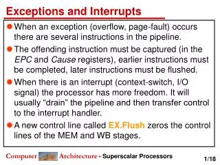
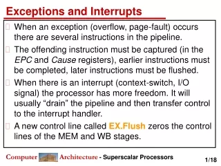
Phase 3 CPU context is saved on SSP as exception stack frame all details CPU needs to return to normal processing nothing saved on reset exception information saved depends on type of exception two types for 68000-68010 six different types for 68020-68040 all save PC and SR Phase 4 load PC with handler address from exception table entry Completion of processing handler executes RTE except reset - nothing to return to Exception Processing (cont.)
Can get exception during exception must prioritize processing Priority groups for 68020-68040 5 groups reset is highest interrupt, trace, coprocessor cleanup are lowest handle most abnormal thing first Priority groups for 68000-68010 3 groups reset, bus error, address error - highest trace, interrupt, illegal instruction, privilege TRAP, CHK, divide by zero - lowest Exception Priority
Reset occurs on power up or total system failure RESET* asserted RESET* and HALT* on 68000 for 10 clock cycles during operation for 100ms after Vdd is stable on power-up for 68000 for 520 clock cycles on power-up for 68020 programmer must set up VBR, MMU, cache, USP then can switch to user mode Reset Logic 555 timer for long power-up pulse button for manual reset will be pressed >> 10 clock cycles Reset Exception
Bus error system fails to complete a bus cycle hardware detects, asserts BERR* pin Examples illegal memory address - no memory at address, write to ROM faulty memory access - error detecting memory had error no VPA* asserted - during synchronous bus access memory privilege violation - e.g. due to page fault Rerun cycle when BERR* and HALT* asserted together usually allow one retry Bus error handling - usually page faults 68010 and later can continue instruction with RTE address error - cannot RTE, would just cause another bus error use stack frame info to emulate bus cycle, avoid original error Bus Error Exception
Interrupt hardware 8 to 3 line priority encoder - generate 3-bit priority level tie off input 0 7 active-low interrupt request lines 1 for each interrupt priority level resistor pullups, open collector pulldowns on peripherals can wire-OR several peripherals to each priority level example - peripherals 2 and 3 are both level 2 peripheral pulls down on line when it wants an interrupt Interrupts are edge sensitive IPL2-IPL0 must change to notice interrupt if level 7 is already being processed, will not notice another one until serviced peripheral releases IRQ7* and new device pulls it down Interrupt Exception
Interrupt acknowledge after accepting interrupt, processor runs IACK bus cycle A modified read cycle put out 111 on FC2-FC0 put out interrupt level accepted on A(3:1) address lines decode into IACK1* to IACK7* lines to peripherals device puts interrupt vector number on D(7:0) and asserts DTACK* puts $0F if uninitialized causes unitialized interrupt vector exception CPU uses vector number to access exception vector table normally vector numbers 64-255 - user-defined vectors Vectored Interrupt
Older peripherals cannot supply interrupt vector 8-bit peripherals Assert VPA* to indicate autovectored interrupt instead of DTACK* in vectored interrupt use AVEC* pin on 68020 and later Autovectors vector determined by interrupt priority level vector numbers 25-31 correspond to interrupt levels 1-7 Multiple requests at same priority handler does not know who requested interrupt must poll each device (test interrupt bit in status register) Hardware add gate to generate VPA* for autovectored devices Autovectored Interrupt
System hangs, want to avoid using reset button Connect debounced switch to IRQ7* line pull down on IRQ7* when switch pushed use autovectored interrupt, since switch cannot supply vector vector 31 routine handles interrupt example - go to monitor or debugger use IACK7* to remove IRQ7* request Manual Interrupts
ILLEGAL instruction special illegal instruction opcode $4AFC generates illegal instruction exception BKPT illegal instructions (68010 and later) BKPT #<data> for data = 0 to 7 corresponds to opcodes $4848 to $484F take illegal instruction exception execute special breakpoint bus cycle before exception call dummy read cycle with FC2-FC1 = 111, A(31:5,1:0) low A(4:2) have breakpoint number on 68020 and later use to trigger logic analyzer external hardware can supply replacement instruction executed instead of illegal instruction exception Breakpoints
Trace exception after each instruction if T-bit set T-bit only set in supervisor mode make TRAP call to set it ORI.W #$8000,(SP) Set T-bit of SR on stack RTE Return to user mode User must supply trace handler arguments what to trace e.g. dump registers on condition print variable when modified 68020 and later has two trace bits regular trace mode trace only on program flow change BRA, JMP, TRAP, RTS, etc. instructions whenever SR is modified Trace Exceptions
Line A exception opcodes $AXXX call vector 10 exception handler XXX are user-definable bits can encode new instructions, handler implements them LEA 2(SP),A0 A0 points to address of instruction following exception MOVEA.L (A0),A0 Read address MOVE.W -2(A0),D0 Read instruction $AXXX then execute based on XXX Use to implement new instructions an extension facility Line F exception opcodes $FXXX call vector 11 exception handler use to implement coprocessor instructions can use when coprocessor is missing Emulator Mode Exceptions
TRAP #<data> <data> = 0 to 15 cause exception numbers 32 to 47 TRAPV - trap on overflow causes vector 7, special form of TRAP Means for user programs to call operating system put system-specific code in trap handler Can pass arguments in registers or on stack e.g. string to put out on serial line Get results back in registers or stack e.g. string read from terminal TRAP Exceptions
Device interrupts with specific handlers or through general handler can treat devices like other tasks to run Timed interrupts signal to switch between tasks - the time slice generate with timer peripheral at regular intervals Scheduler get interrupt, determine task to be executed devices needing service can be considered task to run Interprocess communication e.g. shared memory locations Real-Time Processing