Download
1 / 99
1.01k likes | 1.16k Views
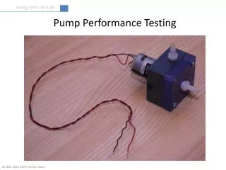
Performance Testing. Knowledge Objectives. Describe the requirements for the performance tests as required by NFPA 1911. Describe the criteria for re-rating fire pumps. Skills Objectives (1 of 2). Perform the no-load governed engine speed test. Perform the pump shift indicator test.

E N D
Knowledge Objectives Describe the requirements for the performance tests as required by NFPA 1911. Describe the criteria for re-rating fire pumps.
Skills Objectives (1 of 2) Perform the no-load governed engine speed test. Perform the pump shift indicator test. Perform the pump engine control interlock test. Perform a gauge meter test. Perform a flow meter test. Perform a tank-to-pump flow test.
Skills Objectives (2 of 2) Perform a vacuum test. Perform an internal relief valve test. Perform a priming system test. Conduct the pumping and overload tests for fire pumps. Perform the pressure control tests.
Introduction (1 of 7) An apparatus accepted and placed in service must be properly inspected, operated, maintained, and tested over its lifetime. Pumping system delivers certain amount of water at desired pressure Pump’s failure to deliver required water at certain pressure impairs fire-suppression ability and safety of fire fighters
Introduction (2 of 7) An apparatus is subject to annual performance testing. Certification testing can be done by agencies other than the UL. Critical that apparatus be tested periodically by independent, third-party certifying agency
Introduction (3 of 7) Performance tests are conducted after the apparatus is put into service to determine if its performance meets predetermined specs or standards. Performance testing of pumps is integral and a vital part of apparatus safety and maintenance.
Introduction (4 of 7) Insurance Services Office (ISO) reports that fire is still the leading cause of loss cited with personal and commercial property insurance policies. Definite correlation between improved fire protection and compliance with NFPA standards ISO Fire Suppression Rating Schedule assigns the highest point total to apparatus pumps.
Introduction (5 of 7) NFPA 1911, Standard for the Inspection, Maintenance, Testing, and Retirement of In-Service Automotive Fire Apparatus, calls for annual service testing of apparatus pumps Fire pumps have a rated capacity of 250+ GPM (1000+ L/min) at 150 psi (1000 kPa) net pump pressure. Test fire pumps yearly to determine if they are still able to achieve designed performance.
Introduction (6 of 7) Performance tests test the entire system. Engine, transmission, pump, and related accessories and devices used in operating the pumping system “Stress test” for the apparatus To pass, the apparatus must: Deliver original design flow and pressure Show no signs of overheating, loss of power, or over-acceleration Not exhibit other major defects
Introduction (7 of 7) The test should be annual for all apparatus with a fire pump with 250+ GPM capacity or if the pump and/or engine has been repaired or modified. The test is not the same as the “New Apparatus Acceptance or UL Test,” which is by an independent agency for the manufacturer. NFPA 1911 calls for a test when major repairs or modifications are made to the pump or a component of the apparatus used in pump operations.
Fire Apparatus Requirements (1 of 6) Engine-driven accessories should not be disconnected or inoperative during the annual performance test. If a chassis engine drives the pump, all headlights, running lights, warning lights, and air conditioners should operate during the pumping portion of the test.
Fire Apparatus Requirements (2 of 6) Devices turned off or not operated during the pump performance test Aerial hydraulic pump Foam pump Hydraulic-driven equipment Winch Windshield wipers Four-way hazard flashers Compressed-air foam system compressor
Fire Apparatus Requirements (3 of 6) If electrical loads are connected through an automatic electrical load management system, the system should automatically disconnect loads during the test. When operating the pump, the engine temperature must be kept within a proper range. Neither cold nor excessively hot engine will give good service
Fire Apparatus Requirements (4 of 6) Watch the oil pressure to see that the engine is properly lubricated. Monitor the transmission gears for overheating. Note and manage engine or pump vibration or leaks in pump casing or connections.
Fire Apparatus Requirements (5 of 6) Use side intakes only when performance testing the fire pumps. May use front- or rear-mounted intakes with side intake suction(s) for all pumps providing flows of 1500+ GPM Keep all other intakes closed and properly capped. Remove Storz fittings before testing. Replace with steamer caps during the test.
Fire Apparatus Requirements (6 of 6) In case of apparatus failure, leave time for repairs. “Failure” is defined as a cessation of proper functioning or performance. Document other defects in the engine or pump performance. Correct minor defects immediately if possible. If repairs cannot be done on site, reschedule apparatus testing for later.
Environmental Requirements (1 of 3) Before beginning tests on pumps, determine and record the environmental conditions Ambient air temperature Water temperature Atmospheric pressure NFPA 1911 specifies tests be conducted when ambient air temperature is 0°F to 110°F (–18°C to 43°C) Days with moderate temperatures are ideal.
Environmental Requirements (2 of 3) Warm water is more likely to cavitate inside the pump. May result in a loss of 500 GPM (1900 L/min) in flow rate Cold water is more likely to freeze and foul the test equipment, especially if the air temperature is also low. Recommend a water temperature of 35°F to 85°F (1.7°C to 29°C); 60°F (16°C) is ideal
Environmental Requirements (3 of 3) To correct local atmospheric pressure readings to sea level, add 1 in. Hg (25 mm Hg) for every 1000’ (305 m) of elevation at the site. High pressure pushes harder on the surface of the water being drafted, making it easier to lift. Low pressure makes it hard to lift. If environmental conditions are not within specified limits, delay the test.
Test Site (1 of 7) The test site should be on an improved roadway or solid ground with water 4–8’ (1.2–2.4 m) below grade. Water should be 4+’ (1.2+ m) deep at the strainer to provide clearance below and sufficient depth above. Conduct all tests requiring flowing water with the pump drafting.
Test Site (2 of 7) When a suitable drafting site is not available, a chosen site must provide a level area, a source of water, and a discharge area. Site elevation and lift should be recorded. Lift is the vertical height that water must be raised during drafting. Maximum lift is the greatest elevation difference at which the apparatus can draft required water under established characteristics of operation
Test Site (3 of 7) The rated capacity of the pump determines: Suction arrangement Diameter of the suction hose Maximum number of suction lines Maximum allowable lift
Test Site (4 of 7) Characteristics to consider for maximum lift: Pump design Engine adequacy Condition of the pump and engine Size and condition of the suction hose and strainers Pumping site elevation above sea level Atmospheric conditions Water temperature
Test Site (5 of 7) Fire departments that want the best pump performance should consider other factors when conducting performance tests. Select a test site with adequate clear, fresh water. Salt water is denser than fresh water and should not be used in tests. Avoid muddy water since it contains hidden debris and can clog the pump, valves, fittings, and gauge lines.
Test Site (6 of 7) Make sure the water source allows good performance and easy accessibility. Apparatus should be able to park on a level, hard surface. A properly designed pump test pit is an option in conducting performance testing. If using a test pit, make sure the usable pit capacity is 10+ gal for every 1 GPM of the pump. Pits with less capacity can result in air entrapment and excessive water temperature rise.
Equipment Requirements (1 of 5) Before conducting performance tests on apparatus, AHJ must ensure the availability of proper equipment and satisfactory working conditions Equipment needed during testing One 0–300 psi test gauge One 0–30 in Hg vacuum gauge Two 0–150 psi test gauges Two Pitot gauges
Equipment Requirements (2 of 5) Equipment needed during testing (continued) One or more flow meters in lieu of Pitot gauges Assorted smooth-bore testing nozzles Mechanical or digital hand-held tachometer Strobe-type tachometer and tape if the apparatus does not have a pump shaft Suction hoses of appropriate sizes and lengths One or more mallets Two deluge appliances with stream straighteners
Equipment Requirements (3 of 5) Equipment needed during testing (continued) Numerous lengths of 2½ (64-mm) or 3 (76-mm) hoses Two wheel chocks Assorted wrenches and Allen keys Roll of plumber’s tape Assorted spanner wrenches Hydrant wrench Calculator
Equipment Requirements (4 of 5) Nozzles for testing are found in the department’s regular equipment. Should know the actual coefficient of discharge of each nozzle Choose a nozzle size to give the desired discharge at a nozzle pressure of 60–70 psi (410–480 kPa). Use only smooth-bore nozzles. Pitot tube with air chamber and pressure gauge is necessary for determining velocity pressure of the water at the nozzle
No-Load Governed Engine Speed Test (1 of 4) Check governed engine speed. If not within ±50 rpm of governed speed when apparatus was brand new, correct the problem before proceeding with the tests. Check speed while preparing the apparatus before the testing day. Failure to operate at the correct governed speed during performance tests is a common problem.
No-Load Governed Engine Speed Test (2 of 4) To get the maximum engine power, run the engine up to the governed engine speed and make sure it stays once the engine reaches a normal operating temperature. Do not let the engine exceed a rated no-load governed speed. Check the air cleaner and fuel filter restrictions and replace filter elements to avoid power loss.
No-Load Governed Engine Speed Test (3 of 4) To get the maximum engine power (continued) Check the fan belt and adjust the tension to provide adequate cooling during the pump performance test. Check that the alternator belt tension and battery charge will provide enough electrical power to allow 45 seconds of uninterrupted primer operation during the vacuum and priming device tests.
No-Load Governed Engine Speed Test (4 of 4) Readings should equal the no-load governed engine speed from when the apparatus was new. Information is listed on the original acceptance form(s), on or near the pump panel on the UL plate.
Intake Relief Valve System Test If apparatus is equipped with an intake relief valve system or combination intake/discharge system, test to ensure the system operates by manufacturer’s specifications Relief valve: device that allows bypass of fluids to limit the system pressure Conduct the test using a second pumper to supply water to the pumper being tested.
Pump Shift Indicator Test Test to verify the pump shift indicators in the cab and on the panel indicate the correct status when the pump is shifted from road to pump mode. Pump shift indicators in the cab and on the pump panel require an electromechanical device to sense the pump shift status.
Pump Engine Control Interlock Test (1 of 2) 1991 NFPA 1901 required an interlock system on any apparatus equipped with electronic or electric engine throttle controls to prevent engine speed advancement. Unless chassis transmission is in neutral with the parking brake engaged Or unless the parking brake is engaged, the fire pump is engaged, and the chassis transmission is in pumping gear Or unless apparatus is in “Okay to pump” mode
Pump Engine Control Interlock Test (2 of 2) NFPA 1911 standard requires testing interlock in only two configurations. Various combinations for arranging chassis, transmission gear, parking brake, and pump shift in driving compartment Engine speed control should be adjustable at the panel when using that combination.
Gauge and Flow Meter Test (1 of 3) Can check discharge pressure gauges quickly against test gauges for accuracy Cap individual discharge lines with gauges and open the discharge valve slightly. Test gauge, master discharge gauge, and all other discharge gauges should have the same reading.
Gauge and Flow Meter Test (2 of 3) Check each water pressure gauge or flow meter for accuracy. Check pressure gauges at at least three points 150 psi (1034 kPa) 200 psi (1379 kPa) 250 psi (1723 kPa) Any gauge off by more than 10 psi (69 kPa) must be recalibrated, repaired, or replaced.
Gauge and Flow Meter Test (3 of 3) Check flow meters (flow minders) individually using hose stream with smooth-bore tip and Pitot tube to measure actual flow Check each flow meter for accuracy at the flows included in the test. Most flow meters can be recalibrated using a small screwdriver or magnet during the test. Follow the manufacturer’s recommendations when recalibrating the flow meter.
Tank-to-Pump Flow Test Compare flow rate with rate designated when apparatus was new or with rate established in previous testing Rates less than previously established indicate problems in tank-to-pump line or tank pump For tanks with capacities greater than 750 gal (2840 L), use the same test except use the flow of 500 GPM (1890 L/min).
Vacuum Test (1 of 3) Pump on the new apparatus must be able to develop a vacuum of 22 in. Hg (75 kPa) Unless the altitude is greater than 2000’ (610 m) The vacuum inside the pump or suction hose should not drop more than 10 in. Hg (34 kPa) in 5 minutes.
Vacuum Test (2 of 3) Vacuum test is a test of the priming system: tests pump tightness, including valves and fittings Not a test of the pump’s ability to maintain vacuum while pumping water Use the required vacuum based on elevation above sea level as noted in NFPA 1911
Vacuum Test (3 of 3) Leaking gaskets and improperly adjusted pump packing are two problems on the test, so preparation of the apparatus is important. If the primer device fails to produce a vacuum of at least 22 in. Hg (75 kPa) at sea level, determine and correct the reason for the discrepancy before conducting further testing.
Priming System Test (1 of 3) At the start of the vacuum test, pay attention to the ease with which the pump develops a vacuum. Before priming, close all discharges, drains, and water tank valves and petcocks. Make sure the gaskets in the suction line hose(s) are in place and free of foreign matter. Close the intake valves. Tighten the intake caps and couplings.
Priming System Test (2 of 3) For pumps operating at less than 1500 GPM (5678 L/min), a priming device should create the necessary vacuum in 30 seconds to lift water 10’ (3 m) through 20’ (6 m) of suction hose of an appropriate size. Priming device on pumps of 1500+ GPM should accomplish this task in 45 seconds
Priming System Test (3 of 3) Might need extra 15 seconds where pump system includes auxiliary 4+” (100+ mm) intake pipe with volume of 1 ft3 (0.03 m3) or more Operate controls to develop pressure, then open one discharge valve to permit water flow. If pump does not pull draft in specific time, note the cause and adjustment and/or repair as necessary.