Download
1 / 16
160 likes | 230 Views
MTA RF Status 01/31/ 2007 NF&MCC Meeting UCLA. A. Moretti. Purpose of the 805 and 201 MHz testing in the MTA. The 805 MHz testing is a continuation of the 805 MHz testing conducted in Lab G with the addition of a 201 MHz test facility. The purpose being:

E N D
MTA RF Status01/31/ 2007NF&MCC MeetingUCLA A. Moretti
Purpose of the 805 and 201 MHz testing in the MTA • The 805 MHz testing is a continuation of the 805 MHz testing conducted in Lab G with the addition of a 201 MHz test facility. The purpose being: • Study Breakdown Limit of Vacuum Cavities. • Study Dark Current and X-Ray emissions at high gradient • Study the effect of High Magnetic on Breakdown, Dark Current and X-Ray emissions • Study Fast Muon Detectors in this environment. • Study in the Button cavity methods to reduce dark current with different materials, coatings and processing using small insertable samples ( Buttons). A. Moretti, NF&MCC Meeting, UCLA
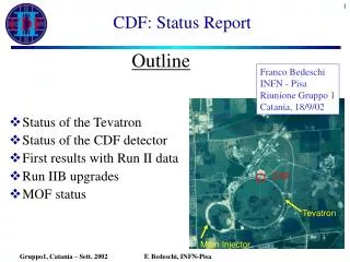
Description of the Experimental Setup Linac Type Modulator and Controls • 12 MW 805 MHz Klystron system and 100 m Waveguide run and 5 MW 201 MHz system with 120 m 0.23 m Coaxial cable run. • Cavity High Vacuum System • Cavity cooling Water System • 5.0 T Solenoid • Support Cryogenic System • X-Ray Shielded Cave and X-Ray monitors Surrounding the cavity. • Interlocked RF with Sparking, Cavity Vacuum and External X-Ray level. • Clean room for preparing samples. A. Moretti, NF&MCC Meeting, UCLA
Experimental Layout 5 T Solenoid Window 805 MHz Cavity 201 MHz Cavity Detector # 1 1.38 m 2.73 m A. Moretti, NF&MCC Meeting, UCLA
Testing Curved Be Windows coated with TiN. Flat windows were Freq unstable because of EM impulse. Frequency instability stopped by Eddy current brake in Magnetic Field. Curved window have been shown to be frequency stable without magnetic field. 805 MHz Cavity under Test A. Moretti, NF&MCC Meeting, UCLA
Button Cavity to continue the 805 MHz Study with different Materials and Coatings. Vacuumed Sealed Sample Holder Sample Button Material A. Moretti, NF&MCC Meeting, UCLA
LBL 201 MHz A. Moretti, NF&MCC Meeting, UCLA
Picture of MTA Hall and 201 MHz Cavity Current Picture of the MTA Hall showing the 5 T magnet in the foreground and the waveguide RF power input to 805 MHz cavity in back ground is the 201 MHz cavity. 201 MHz cavity during preparation for installation in Aug 05. A. Moretti, NF&MCC Meeting, UCLA
201 MHz 5 MW Amplifier and the 805 MHz 12 MW Klystron 201 MHz 5 MW Amplifier 805 MHz 12 MW Klystron System A. Moretti, NF&MCC Meeting, UCLA
First RF 805 MHz Commissioning without Magnetic Field Last March A. Moretti, NF&MCC Meeting, UCLA
First Radiation Measurement with Magnetic Field compared to No Field Data March 06, Results. Safe E Field Limit ~ 16 MV/m Detector Distance=1.34 m A. Moretti, NF&MCC Meeting, UCLA
Nov. 06 Results: Electric field limit at 2.5 T in the LBLSingle Cell Cavity with Curve Be Windows coated with TiN A. Moretti, NF&MCC Meeting, UCLA
Latest Electric field limit Data at 2.5 T and 1.25 T in the LBLSingle Cell Cavity with Curve Be Windows coated with TiN • The Asymptotic limit line shown indicates the continuous Gradient sparking limit. In all the cases studied including Lab G this line as predicted the Gradient Limit for the cases under Study. • For the 1.25 T case the Save operating limit has been shown to be 20 MV/m Asymptotic Gradient limit line at 1.25 T 1.25 T Data RF Conditioning without Magnetic Field 2.5 T Data A. Moretti, NF&MCC Meeting, UCLA
Comparison of Lab G Results with the MTA Data MTA 1.25 T Result Jan. 07 MTA Result ~ 16 MV/m A. Moretti, NF&MCC Meeting, UCLA
CERN DC Spark Breakdown Compared to 805 MHz Cavity Sparking History of 805 MHz Cavity A. Moretti, NF&MCC Meeting, UCLA
Conclusions and future plans • Results of Lab G have been verified with the curved Be windows in March 06 and in Nov 06 at 805 MHz in the MTA at 2.5 T and In January 07 at 1.25 T. • We need to continue the study to determine the mechanism for the enhancement of Dark Current in Large Magnetic fields: does it increase the number of emitters, the electric enhancement factor, or both? • The button cavity will be used to study these and other questions: materials, coatings, etc. Plans are underway to install the Button cavity and begin these studies. • Studies on the 201 MHz cavity are continuing and plans are underway to move it close to magnet to be in as high as fringe field as possible. A. Moretti, NF&MCC Meeting, UCLA