Download
1 / 15
160 likes | 282 Views
Seminar 1, October , 10th 2008. Conceptual model on how to relate geological structures to co-seismic deformation. King et al. , JGR 1988 and Stein et al., JGR 1988. Stein et al., 1988. Lost river Fault, Idaho. Starting Point.

E N D
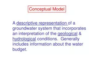
Seminar 1, October, 10th 2008 Conceptual model on how to relate geological structures to co-seismic deformation King et al. , JGR 1988 and Stein et al., JGR 1988
Stein et al., 1988 Lost river Fault, Idaho Starting Point Figure 1: Geological cross section modified from Bond [1978] and Skipp and Harding [1985] using the gravity survey of Mabey [1985] and a seismic-reflection profile of Smithe t al. [1985].
Lost river Fault, Idaho Stein et al., 1988 Figure 1: (a)Coseismic deformation associated with the 1983 Borah Peak, Idaho, M =7.0 earthquake [from Stein and Barrientos, 1985] (b) Geological cross section modified from Bond [1978] and Skipp and Harding [1985] using the gravity survey of Mabey [1985] and a seismic-reflection profile of Smithe t al. [1985]. Starting Point
What is the model useful for? • Understanding the nature of geological deformation • To deduce hidden or erodeed structures : • Estimate fault slip, or slip rate • Estimate recurrence of large earthquakes Aims’ study
Lost river Fault, Idaho Stein et al., 1988 Figure 1: (a)Coseismic deformation associated with the 1983 Borah Peak, Idaho, M =7.0 earthquake [from Stein and Barrientos, 1985] (b) Geological cross section modified from Bond [1978] and Skipp and Harding [1985] using the gravity survey of Mabey [1985] and a seismic-reflection profile of Smithe t al. [1985]. Starting Point
King et al., 1988 Model (1) Figure 2: Deformation due to faulting in the crust
Stein et al., 1988 Model (2) Figure 3: Schematic addition of sudden coseismic and slow interseismic deformation to generate the observed geological structure, modified by erosion (dotted) and deposition (stippled), for a 45 degrees-dipping reverse fault with 1 km of cumulative slip.
King et al., 1988 Coseismic de formation Figure 4 : Coseismic and relaxed deformation for 45 degrees dipping fault associated with no erosion and deposition
Stein et al., 1988 Model (2) Figure 3: Schematic addition of sudden coseismic and slow interseismic deformation to generate the observed geological structure, modified by erosion (dotted) and deposition (stippled), for a 45 degrees-dipping reverse fault with 1 km of cumulative slip.
Stein et al., 1988 Interseismic deformation Figure 5: Contributions of interseismic deformation. Arrow denotes Viscous flow, and cone of sediment represent applied load (negative load due to erosion not shown).
King et al., 1988 Flexure due to a Load Figure 6 : Surface deformation of a gravitating plate overlying a fluid medium due to a localized load. Deformation distributions are normalized to constant maximum displacement. The width (W) corresponds to where the Deformation amplitudes drop to 20% of the maximum displacement.
King et al., 1988 Flexure due to a Load Figure 6 : The influence of flexural rigidity on vertical displacements associated with reverse faulting.
One example: White Wolf Fault, California Stein et al., 1988 Figure 8 : (a) Coseismic deformation associated with the 1952 Kern County M=7.3 earthquake [from Stein and Thatcher, 1981]. ( b) Kern River basin stratigraphy [from Callaway, 1969]. Contemporaneous units used to estimate the fault displacement are darkened.
Stein et al., 1988 Figure 9 : Model fitted to the White Wolf fault. (a)Sediment load measured from observed basin structure. (b) Resulting flexure from loading, and cumulative earthquake cycle (coseismic deformation + postseismic relaxation) after 6.75 km of net slip on the fault, for an elastic thickness of 2 km. (c) Predicted structure (earthquake cycle + flexure due to loading) compared with observed structure from (a) One example: White Wolf Fault, California