Download
1 / 38
380 likes | 576 Views
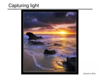
Capturing light. Source: A. Efros. Review. Pinhole projection models What are vanishing points and vanishing lines? What is orthographic projection? How can we approximate orthographic projection? Lenses Why do we need lenses? What controls depth of field? What controls field of view?

E N D
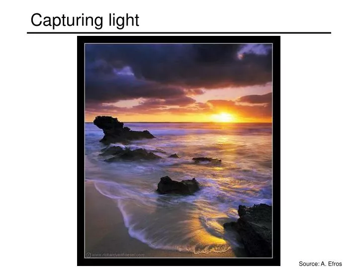
Capturing light Source: A. Efros
Review • Pinhole projection models • What are vanishing points and vanishing lines? • What is orthographic projection? • How can we approximate orthographic projection? • Lenses • Why do we need lenses? • What controls depth of field? • What controls field of view? • What are some kinds of lens aberrations? • Digital cameras • What are the two major types of sensor technologies? • What are the different types of color sensors?
Aside: Early color photography • Sergey Prokudin-Gorsky (1863-1944) • Photographs of the Russian empire (1909-1916) http://en.wikipedia.org/wiki/Sergei_Mikhailovich_Prokudin-Gorskii http://www.loc.gov/exhibits/empire/
Today • Radiometry: measuring light • Surface reflectance: BRDF • Lambertian and specular surfaces • Shape from shading • Photometric stereo
Radiometry • What determines the brightness of an image pixel? Light sourceproperties Sensor characteristics Surface shape Exposure Surface reflectanceproperties Optics Slide by L. Fei-Fei
dA Radiometry • Radiance (L): energy carried by a ray • Power per unit area perpendicular to the direction of travel, per unit solid angle • Units: Watts per square meter per steradian (W m-2 sr-1) • Irradiance (E): energy arriving at a surface • Incident power in a given direction per unit area • Units: W m-2 • For a surface receiving radiance L(x,q,f) coming in from dw the corresponding irradiance is n dω θ
A Solid Angle • By analogy with angle (in radians), the solid angle subtended by a region at a point is the area projected on a unit sphere centered at that point • The solid angle dw subtended by a patch of area dA is given by:
Radiometry of thin lenses • L: Radiance emitted from P toward P’ • E: Irradiance falling on P’ from the lens What is the relationship between E and L? Forsyth & Ponce, Sec. 4.2.3
dA o dA’ Example: Radiometry of thin lenses Area of the lens: Let’s compute the power δPtransmitted from P to the lens: The power δPnow gets concentrated at P’, resulting in irradiance E:
Radiometry of thin lenses • Image irradiance is linearly related to scene radiance • Irradiance is proportional to the area of the lens and inversely proportional to the squared distance between the lens and the image plane • The irradiance falls off as the angle between the viewing ray and the optical axis increases Forsyth & Ponce, Sec. 4.2.3
Radiometry of thin lenses • Application: • S. B. Kang and R. Weiss, Can we calibrate a camera using an image of a flat, textureless Lambertian surface? ECCV 2000.
The journey of the light ray • Camera response function: the mapping f from irradiance to pixel values • Useful if we want to estimate material properties • Shape from shading requires irradiance • Enables us to create high dynamic range images Source: S. Seitz, P. Debevec
Recovering the camera response function • Method 1: Modeling • Carefully model every step in the pipeline • Measure aperture, model film, digitizer, etc. • This is really hard to get right Slide by Steve Seitz
Recovering the camera response function • Method 1: Modeling • Carefully model every step in the pipeline • Measure aperture, model film, digitizer, etc. • This is really hard to get right • Method 2: Calibration • Take pictures of several objects with known irradiance • Measure the pixel values • Fit a function pixel intensity = response curve irradiance Slide by Steve Seitz
pixel intensity = response curve Exposure (log scale) irradiance * time = Recovering the camera response function • Method 3: Multiple exposures • Consider taking images with shutter speeds 1/1000, 1/100, 1/10, 1 • The sensor exposures in consecutive images get scaled by a factor of 10 • This is the same as observing values of the response function for a range of irradiances:f(E), f(10E), f(100E), etc. • Can fit a function to these successive values • For more info • P. E. Debevec and J. Malik. Recovering High Dynamic Range Radiance Maps from Photographs. In SIGGRAPH 97, August 1997 Slide by Steve Seitz
The interaction of light and matter • What happens when a light ray hits a point on an object? • Some of the light gets absorbed • converted to other forms of energy (e.g., heat) • Some gets transmitted through the object • possibly bent, through “refraction” • Some gets reflected • possibly in multiple directions at once • Really complicated things can happen • fluorescence • Let’s consider the case of reflection in detail • In the most general case, a single incoming ray could be reflected in all directions. How can we describe the amount of light reflected in each direction? Slide by Steve Seitz
surface normal Bidirectional reflectance distribution function (BRDF) • Model of local reflection that tells how bright a surface appears when viewed from one direction when light falls on it from another • Definition: ratio of the radiance in the outgoing direction to irradiance in the incident direction • Radiance leaving a surface in a particular direction: add contributions from every incoming direction
Diffuse reflection • Dull, matte surfaces like chalk or latex paint • Microfacets scatter incoming light randomly • Light is reflected equally in all directions: BRDF is constant • Albedo: fraction of incident irradiance reflected by the surface • Radiosity: total power leaving the surface per unit area (regardless of direction)
Diffuse reflection: Lambert’s law • Viewed brightness does not depend on viewing direction, but it does depend on direction of illumination B: radiosity ρ: albedo N: unit normal S: source vector (magnitude proportional to intensity of the source) N S x
Specular reflection • Radiation arriving along a source direction leaves along the specular direction (source direction reflected about normal) • Some fraction is absorbed, some reflected • On real surfaces, energy usually goes into a lobe of directions • Phong model: reflected energy falls of with • Lambertian + specular model: sum of diffuse and specular term
Moving the light source • Changing the exponent Specular reflection
Photometric stereo • Assume: • A Lambertian object • A local shading model (each point on a surface receives light only from sources visible at that point) • A set of known light source directions • A set of pictures of an object, obtained in exactly the same camera/object configuration but using different sources • Orthographic projection • Goal: reconstruct object shape and albedo S2 Sn S1 ??? Forsyth & Ponce, Sec. 5.4
Surface model: Monge patch Forsyth & Ponce, Sec. 5.4
Image model • Known: source vectors Sj and pixel values Ij(x,y) • We also assume that the response function of the camera is a linear scaling by a factor of k • Combine the unknown normal N(x,y) and albedo ρ(x,y)into one vector g, and the scaling constant and source vectors into another vector Vj: Forsyth & Ponce, Sec. 5.4
(n × 1) (n × 3) (3× 1) known known unknown Least squares problem • Obtain least-squares solution for g(x,y) • Since N(x,y) is the unit normal, r(x,y) is given by the magnitude of g(x,y) (and it should be less than 1) • Finally, N(x,y) = g(x,y) / r(x,y) • For each pixel, we obtain a linear system: Forsyth & Ponce, Sec. 5.4
Example Recovered albedo Recovered normal field Forsyth & Ponce, Sec. 5.4
Recall the surface is written as This means the normal has the form: If we write the known vector gas Then we obtain values for the partial derivatives of the surface: Recovering a surface from normals - 1 Forsyth & Ponce, Sec. 5.4
Integrability: for the surface f to exist, the mixed second partial derivatives must be equal: We can now recover the surface height at any point by integration along some path, e.g. Recovering a surface from normals - 2 (for robustness, can take integrals over many different paths and average the results) (in practice, they should at least be similar) Forsyth & Ponce, Sec. 5.4
Surface recovered by integration Forsyth & Ponce, Sec. 5.4
Limitations • Orthographic camera model • Simplistic reflectance and lighting model • No shadows • No interreflections • No missing data • Integration is tricky
Reconstructing surfaces with arbitrary BRDF’s • T. Zickler, P. Belhumeur, and D. Kriegman, “Helmholtz Stereopsis: Exploiting Reciprocity for Surface Reconstruction,"ECCV 2002. • Key idea: switch the camera and the light source
Helmholtz stereopsis • Let’s put the light at or and the camera at ol • Recall that the BRDF ρ(vl,vr) is the ratio of outgoing radiance in direction vl to incident irradiance in direction vr p vl vr n ol or Outgoing radiance: proportional to observed image irradiance Incident irradiance: radiance received from the light multiplied by the foreshortening (cosine) term and by the solid angle (1/d2) term
Helmholtz stereopsis p p • Helmholtz reciprocity: ρ(vl,vr) = ρ(vr,vl) vl vr vl vr n n ol or ol or
Helmholtz stereopsis • The expression w(d)·n = 0 provides a constraint both on the depth of the point and its normal • We get M constraints for M light/camera pairs • These constraints can be used for surface reconstruction: for example, we can search a range of depth values to determine which one best satisfies the constraints…
Example results reciprocal stereo pairs custom stereo rig recovered depth map and normal field original image
Next time: Color Phillip Otto Runge (1777-1810)