1 / 27

ATMega128 I/O Power Control ( Solid State Switch, Relay)

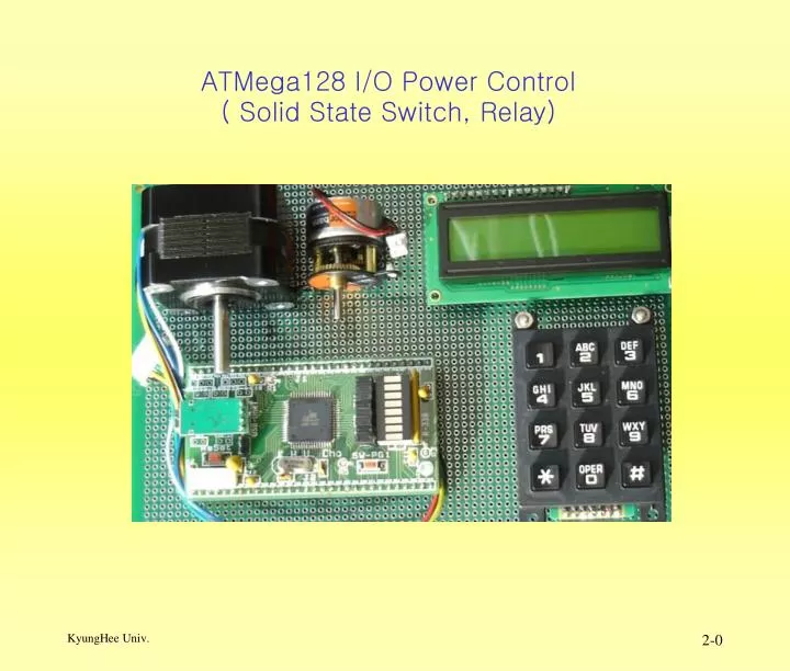
ATMega128 I/O Power Control ( Solid State Switch, Relay). Computer-Controlled Current Switches BJT Transistors. 전류 제어 Switch(BJT ) NPN Transistor Model. PNP Transistor Model. 여러 가지 Relay 예. 8.5.1 Introduction to Relays. 제어 회로와 다른 전원으로 구동하는 Relay 의 예.

maille
Download Presentation

ATMega128 I/O Power Control ( Solid State Switch, Relay)

An Image/Link below is provided (as is) to download presentation Download Policy: Content on the Website is provided to you AS IS for your information and personal use and may not be sold / licensed / shared on other websites without getting consent from its author. Content is provided to you AS IS for your information and personal use only. Download presentation by click this link. While downloading, if for some reason you are not able to download a presentation, the publisher may have deleted the file from their server. During download, if you can't get a presentation, the file might be deleted by the publisher.

E N D

Presentation Transcript


  1. ATMega128 I/O Power Control( Solid State Switch, Relay)

  2. Computer-Controlled Current SwitchesBJT Transistors • 전류 제어 Switch(BJT) • NPN Transistor Model • PNP Transistor Model

  3. 여러 가지 Relay 예

  4. 8.5.1 Introduction to Relays • 제어회로와 다른 전원으로 구동하는 Relay의 예

  5. 여러 가지제어소자의 사진EM, Solid-state, Reed Relay

  6. Electromagnetic Relays 의구조

  7. Electromagnetic Relays Basics • 여러 가지 Relay의 구조 예 • Relay의 구조에 따른 Activation Sequence

  8. Reed Relay의 구조

  9. Solenoid Relay의 구조

  10. Solenoid Relay 사진

  11. Interfacing EM Relays, Solenoids, and DC Motors • Current Sink 구조 예 Snubber diode

  12. EM Relays와 Solenoids의 Interfacing 예

  13. 단 방향 DC Motors Control 회로(HighCurrent MOSFET) 예

  14. Isolated 단 방향 DC Motors Control 회로 예

  15. Isolated 단 방향 DC Motors Control 회로(HighCurrent MOSFET) 예

  16. Isolated 단 방향 DC Motors Control 회로(HighCurrent MOSFET) 예

  17. 양 방향 H-BridgeDC Motors Control 회로 예

  18. Isolated 양 방향 H-BridgeDC Motors Control 회로 예

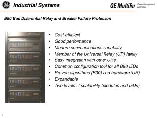
  19. Dual Full-Bridge Driver L298 • High voltage : 46V • high current : 4A • Dual full-bridge driver • Accept standard TTL logic levels • Drive inductive loads such as • Relays, Solenoids, DC and, Stepping motors

  20. L289 Block Diagram M M

  21. L298을 이용한 DC Motor and Stepper Controller L298N Current Motor Supply Logic Current Sensing Voltage Enable Supply Enable Sensing A Out Out Vs In A In GND Vs In B In Out Out B 1 2 1 2 3 4 1 2 3 4 5 6 7 8 9 10 11 12 13 14 15 2 7414 1 4 7414 3 470uF 35V + - +Vout 2 Motor 2 -Vout2 2 2 +Vout 1 Motor 1 -Vout1 1 + 1 + 4 4 Vs Supply Voltage GND 2W06 2W06 Vs Supply Voltage GND Vs 3 3 104 1 2 3 4 5 6 GND Dir1 En1 Dir2 En2 Vcc In Put Control Signal Connector

  22. Solid-State Relay(Triac)

  23. Stepper Motors

  24. Stepper Motors Interfacing 예

  25. Stepper motor controlsequence 예

  26. Double Circular Linked List를 이용한 Stepper Motors 제어 Data Structure

  27. L293 Driver를 이용한 Stepper Motor Interface 예

More Related