Download
1 / 20
200 likes | 334 Views
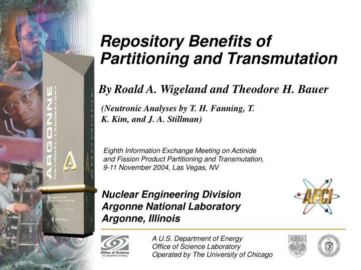
Repository Benefits of Partitioning and Transmutation. (Neutronic Analyses by T. H. Fanning, T. K. Kim, and J. A. Stillman). By Roald A. Wigeland and Theodore H. Bauer.

E N D
Repository Benefits of Partitioning and Transmutation (Neutronic Analyses by T. H. Fanning, T. K. Kim, and J. A. Stillman) ByRoald A. Wigeland and Theodore H. Bauer Eighth Information Exchange Meeting on Actinide and Fission Product Partitioning and Transmutation, 9-11 November 2004, Las Vegas, NV
Outline/ Goals • Examine spent fuel treatment options that could allow the loading density of a geologic repository to be increased (with potential benefits of increased area loading or smaller repository sites with reduced environmental impact). • Identify the partitioning and transmutation strategies that result in large repository loading benefits. • Quantify repository loading benefits achievable through limited recycling in LWRs • Use the proposed Yucca Mountain Repository as a specific example for quantitative studies.
The Yucca Mountain Repository (From Yucca Mountain Project Reports)
Proposed layout (From Yucca Mountain Project Reports)
Repository Cross-Section Design:High-Temperature Operating Mode- (HTOM) • Drifts (tunnels) assumed cooled by forced-air ventilation for ~75 years before closure. • Repository loading limits are determined by temperature limits at various locations and times and the heat source from stored waste. (Figure 2-6 in the Final Environmental Impact Statement)
Temperature LimitsEnsure Integrity of Barriers to Radionuclide Release • Most restrictive HTOM temperature limits: • Peak rock temperature midway between adjacent drifts must remain below the local boiling point (96 oC). • Peak rock temperature at drift walls must remain below 200 oC. • Loading limits determined by calculating temperatures generated in the drift and mountain before and after closure. • A detailed thermal model was developed describing a “unit cell” slice of Yucca Mountain surrounding a storage drift. • Yucca Mountain thermophysical properties assumed throughout • Parameter uncertainties not included in these studies. • Focus is on relative assessments of maximum drift loading for different chemical separation options.
Geometry and Node Structureof the Thermal Model’s “Unit Cell”
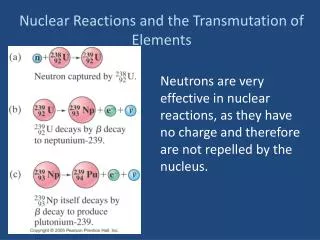
Characteristics of theSpent Fuel Heat Source • Discharged PWR fuel assumed representative of the majority of spent fuel destined for geologic disposal. • Decay heat drops rapidly after discharge from the reactor. • First 60 years of decay heat predominantly from fission products barium and yttrium as decay products of cesium and strontium. • After 60 years, decay heat predominantly from actinide elements, plutonium and americium. • After ~200 years, decay heat drops much more slowly. • Heating almost entirely from plutonium and americium, out to at least 10,000 years. • The much slower decrease with time is due to the relatively long half-lives of the isotopes 241Am, 238Pu, 239Pu, and 240Pu.
Repository Benefit: Quantified by Comparing Maximum Drift Loadings to PWR Baseline Values. • The thermal model calculates a baseline maximum linear loading of waste in a drift of ~1.1 MTIHM/m or ~55 GWd/m. • Limited by the 96 ºC peak maximum temperature midway between adjacent drifts at ~1600 years. • With key actinide elements Am and Pu removed calculated maximum linear loading is ~5.9 MTIHM/m or ~295 GWd/m. • Limited by the 200 ºC peak temperature allowed at the drift wall shortly after repository closure. • With key fission product (Cs & Sr) and actinide (Am & Pu) elements removed calculated maximum linear loading is ~47 MTIHM/m or ~2350 GWd/m. • Limited by the 200 ºC peak temperature allowed at the drift wall at the time of emplacement.
Baseline Thermal Analysis forDirect Disposal of Spent PWR Fuel
Requirements for Large Repository Loading Benefits • All waste streams from processing spent fuel should have ≥99% Pu, Am, Cs, and Sr removed before being sent to the geologic repository. • It is practical to store separated Cs and Sr for several hundred years without a geologic repository. • The inventory of separated long-lived Pu and Am actinide isotopes can only be reduced by transmutation. • Transmutation is possible by recycle in either “fast neutron” or “thermal neutron” reactors.
Loading Benefits fromNear-Term Recycle in LWRs • Recycle of actinides in thermal neutron systems reduces inventories of both heat-generating and fissile isotopes. • Three schemes were examined that differ in the way that fissile content is provided to recycled assemblies. • MOX: Within a UO2 matrix, recycled Pu, Am, and Np from multiple assemblies at each step provides the needed fissile content for a single next step assembly; fertile UO2 breeds more fissile during irradiation. • IMF: Same as “MOX”, but within an inert (non-fertile) ZrO2 matrix. • CORAIL-PNA (MOX-UE): In a UO2 matrix, recycled Pu, Am, and Np from a single assembly supplemented by higher enriched UO2 provides the needed fissile content for a single next step assembly. • Number of recycles was a parameter in the study. • Calculated benefit compares maximum drift loadings in GWd/m to the PWR baseline.
Calculated Repository Benefit vs Number of LWR Recycles • Two waste streams assumed sent to the repository: (1) Recycle process waste containing 1% of generated Pu, Am, Np, Cs, & Sr. (2) Untreated spent fuel from the last recycle step.
Results and Implications • By itself, the process waste stream yields a large (≥40) repository loading benefit. • But direct disposal of “hot” spent fuel from the last recycle reduces net loading benefits down to factors ~2 at most. • Thus, large repository benefits require that: • Separation and recycling of selected actinides and fission products be continued, and… • Untreated spent fuel should never be sent to the repository. • Note that fast reactors are capable of recycling continuously- but not all LWR schemes. • “MOX” and “IMF”– probably not. • “CORAIL-PNA (MOX-UE)” –yes, but requires enriched uranium feed.
Continuous Actinide Recycle- Needed for Large Loading Benefit
Conclusions • Large repository loading benefits result if ≥99% of Pu, Am, Cs, and Sr is removed from spent fuel waste streams. • A similar result should apply to loading any geologic repository where heat load is an issue - not just Yucca Mountain. • Large repository loading benefits can be available immediately by: • Processing spent fuel. • Providing temporary storage for selected elements prior to recycling. • Sending only the process waste to the repository. • Limited recycling in LWRs can provide a useful lead-in to continuous recycling in future fast spectrum reactors.