Download
1 / 23
240 likes | 247 Views
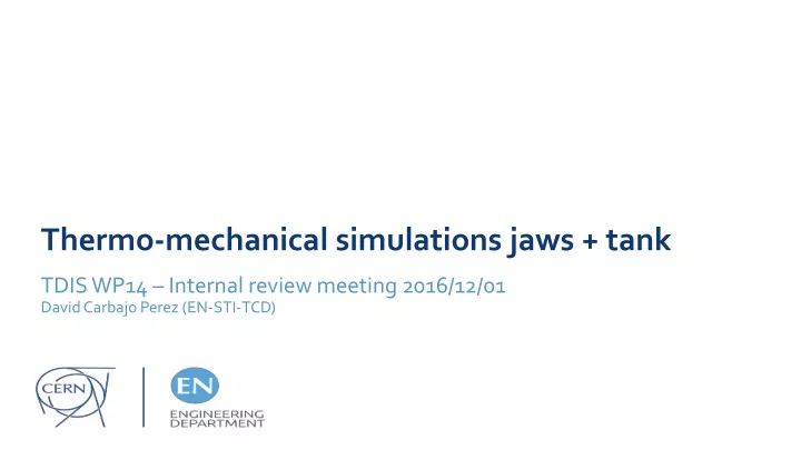
Thermo-mechanical simulations jaws + tank. TDIS WP14 – Internal review meeting 2016/12/01 David Carbajo Perez (EN-STI-TCD). Thermo-mechanical simulations jaws + tank. Introduction Jaws material definition Loads scenarios overview RW heating Vacuum tank simulation Summary

E N D
Thermo-mechanical simulations jaws + tank TDIS WP14 – Internal review meeting 2016/12/01 David Carbajo Perez (EN-STI-TCD)
Thermo-mechanical simulations jaws + tank Introduction Jaws material definition Loads scenarios overview RW heating Vacuum tank simulation Summary Annex: temperature distribution plots
Thermo-mechanical simulations jaws + tank Introduction • Several simulations conducted to assess mechanical strength of the different jaw components against potential beam impacts. • Base for such studies is the output of Fluka energy deposition analysis presented by Matthias Immanuel Frankl. • In addition, thermal impact on the jaws due to impedance phenomena has been simulated. • Last but not least, vacuum tank structural simulation results are presented
Thermo-mechanical simulations jaws + tank Material definition overview 8 5 6 7 4 3 2 1 TDIS Jaw cross-section view
Thermo-mechanical simulations jaws + tank Run3 Standard beam - 2mm orbit error Pulse bunches: 288 Pulse protons: 6.624E13 Pulse time: 8.175 µsec Loads scenarios overview P2 P8 Same conditions as P2
Thermo-mechanical simulations jaws + tank Run3 Standard beam - 2mm orbit error Pulse bunches: 288 Pulse protons: 6.624E13 Pulse time: 8.175 µsec Loads scenarios overview – Shower effect on jaws U – upstream / M- middle / D- downstream
Thermo-mechanical simulations jaws + tank Loads scenarios overview – Shower effect on jaws Stiffener - Plastic strain ca. 0.3% Stiffener - Temperature distribution U – upstream / M- middle / D- downstream
Thermo-mechanical simulations jaws + tank Loads scenarios overview – Shower effect on jaws Cooling pipes – temperature distribution Cooling pipes – plastic strain ca. 0.2% U – upstream / M- middle / D- downstream
Thermo-mechanical simulations jaws + tank Loads scenarios overview – Focus on blocks Applicable for both P2/P8
Thermo-mechanical simulations jaws + tank Loads scenarios overview – Focus on blocks Applicable for both P2/P8 As indicated in the table 11, tensile stresses can reach up to 37 MPa (BCMS beam) in the case of the Graphite R4550. It must be noticed that measurements at EN/MME Mechanical Lab have revealed higher yield strength values that the ones shown there. In the case of 3D C/C the safety margin is larger For further details please refer to documents EDMS 1458583 (https://edms.cern.ch/ui/file/1458583/0.4/LHC-TCDI-ES-0004-00-04.pdf) TDI thermo-mechanical simulations: Boron Nitride versus Graphite 235th LHC Machine Committee 16/09/2015)
Thermo-mechanical simulations jaws + tank Loads scenarios overview – Focus on blocks Applicable for both P2/P8 Since the yield strength of the block Aluminum alloy drops after the bake-out stage down to 110 MPa (at room temperature) the stress level highlighted in the analysis turns out to be too high. As alternative, Titanium was evaluated showing much better results. No weakness detected on copper blocks.
Thermo-mechanical simulations jaws + tank RW heating Resistive wall heating effect takes place while the beam passes between the jaws. The considered input cycle is represented hereunder Estimated total power loss injection : 1250 W ( 30% higher in case of 3D C-C! ) Beam injection Beam circulation 5 hours 45 min. Temperature evolution of the graphite
Thermo-mechanical simulations jaws + tank RW heating Resistive wall heating effect takes place while the beam passes between the jaws. It induces temperatures of 40°C in the graphite during injection and less than 30°C maintained over the beam circulating period. Estimated total power loss injection : 1250 W ( 30% higher in case of 3D C-C! ) Cooling system water temperature: 27°C Heat flux
Thermo-mechanical simulations jaws + tank Vacuum tank simulation Most critical conditions take place at bake-out stage. Max. stress level (63 MPa) is reached at the edges of the largest-area => lower than yield strength (100 Mpa) Material: AISI Type 304L Stainless Steel (grade 1.4306)
Thermo-mechanical simulations jaws + tank Vacuum tank simulation Displacement of the pins that support the platines with the jaws : u1 u2 u3 u4 l1 l2 l3 l4 Material: AISI Type 304L Stainless Steel (grade 1.4306)
Thermo-mechanical simulations jaws + tank Summary • Stresses at the stiffener are on the borderline. Reinforcement options are currently under analysis • Cooling pipes expected to have a small amount of plastic deformation not critical for the function though. On the other hand, alternative materials such us pure nickel or pure copper will be assessed for thermal efficiency improvement • Graphite R4550 shows sufficient strength to be used as material for primary absorbing blocks • Aluminum absorbing blocks shall be upgraded to titanium ones (further simulations are in any case needed) • RW heating lead to over-time maintained temperatures lower than 30°C • No weakness detected on vacuum tank strength. Pins displacement below admissible threshold
Thermo-mechanical simulations jaws + tank THANKS FOR YOUR ATTENTION
Thermo-mechanical simulations jaws + tank P8 central impact. Upstream upper jaw Annex: temperature distribution plots stiffener
Thermo-mechanical simulations jaws + tank P8 central impact. Middle upper jaw Annex: temperature distribution plots stiffener
Thermo-mechanical simulations jaws + tank P8 central impact. Downstream upper jaw Annex: temperature distribution plots
Thermo-mechanical simulations jaws + tank Annex: temperature distribution plots P2 central impact. Upstream upper jaw
Thermo-mechanical simulations jaws + tank Annex: temperature distribution plots P2 central impact. Middle upper jaw
Thermo-mechanical simulations jaws + tank Annex: temperature distribution plots P2 central impact. Downstream upper jaw