Download
1 / 54
540 likes | 627 Views
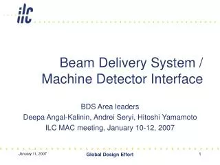
ILC Interaction Region and Machine Detector Interface. Andrei Seryi, SLAC. representing BDS Area leaders Deepa Angal-Kalinin, Andrei Seryi, Hitoshi Yamamoto MDI panel and BDS team. Contents.

E N D
ILC Interaction Region and Machine Detector Interface Andrei Seryi, SLAC representing BDS Area leaders Deepa Angal-Kalinin, Andrei Seryi, Hitoshi Yamamoto MDI panel and BDS team Global Design Effort
Contents • Will describe design of Beam Delivery System, focusing in particular on Machine Detector Interface aspects • IR hall and surface buildings • Detector assembly • Machine background • Design of IR and detector • IR arrangements for two detectors Global Design Effort
BDS layout Global Design Effort
IR hall region Global Design Effort
BDS beam-line layout Polarimeter BSY Sacrificial collimators b-collim. service tunnel E-collimator Diagnostics FF 14mr IR Tune-up dump 5m E-spectrometer Muon wall Extraction -2.2km Global Design Effort
BDS optics IR linac Upstream polarimeter; b & E –collimation ; Energy spectrometers are of particular MDI interest Global Design Effort
BDS parameters Global Design Effort
On-surface assembly of ILC detectorsCMS approach • CMS assembly approach: • Assembled on the surface in parallel with underground work • Allows pre-commissioning before lowering • Lowering using dedicated heavy lifting equipment • Potential for big time saving • Reduces size of required underground hall Global Design Effort
ILC Underground schedule Earlier version of layout Global Design Effort
On-surface assembly of ILC detectors • Adopted CMS on-surface assembly approach for ILC detector • This allows saving more than two years and fitting into the goal of “7years until first beam” and “8years until physics run” • CMS assembly and lowering the detectors parts in the hall is presently ongoing, according to the plan • Information and images on next pages are courtesy of CERN colleagues Alain Herve, Martin Gastal, et al. Global Design Effort
CMS Assembly Global Design Effort
CMS Assembly Global Design Effort
CMS Assembly Global Design Effort
CMS Assembly Global Design Effort
CMS Assembly Global Design Effort
CMS Assembly Global Design Effort
CMS Assembly Global Design Effort
CMS Assembly Global Design Effort
CMS Assembly February 1. Lowering down a 1200 ton barrel ring. Photo and info courtesy Alain Herve Global Design Effort
CMS Assembly Lowering down a 1200 ton barrel ring CMS is at half process. Next -- lowering 2kt central barrel by the end of February. Alain Herve Global Design Effort
Optimization of IR hall and assembly procedure • For RDR, discussing possible variations of assembly procedure • pure and modified CMS assembly (configs. A and B in the table on next slide) • Difference being how large pieces are assembled on surface • Present RDR does not intend to finalize all the details for the schedule, hall sizes, capacity of cranes, etc. • Optimization will be done in details by BDS, CF&S and Detector concept groups in EDR phase Global Design Effort
Table of IR assumptions continued … Global Design Effort
… continued … Global Design Effort
Included in IR hall and surface buildings: • IR hall: • detectors hall of 120x25x39m • service cavern 40x15x10m • finished civil engineering works, plus • movable concrete shielding wall in two parts (on air pads) • steel platforms with staircases and all fittings • two 1.6t elevators between steel platforms plus two 2.8t in shafts, • steel plates on the floor of the Hall • one 400t and two 20t overhead cranes in Hall • etc… • Included in surface assembly building: • two assembly buildings 100x25x25m • 400t and 20t overhead cranes • This choice can suite some detectors better than other (one size does not fit all) and may cause some concerns • Further adjustments of IR hall and surface buildings will be done, in close connection with detector colleagues, during EDR phase Global Design Effort
IR surface area Global Design Effort
Next slides • Will discuss • Machine background • muons • Synchrotron Radiation • Beam-gas • Extraction line losses • IR design • Detector Integrated Dipole (DID) • Antisolenoids Global Design Effort
BDS layout & possible sources of muons SP2 SP4 betatron collimation septa MPS coll skew correction / emittance diagnostic polarimeter fast kickers fast sweepers tuneup dump beta match final focus polarimeter energy collimation SPEX IP primary dump energy spectrometer fast sweepers clean-up collimators muon wall energy spectrometer final doublet Global Design Effort
Muon reduction N.Mokhov et al., FNAL • Muon flux in BDS & IR with and without 5m muon wall • Allows reducing flux in TPC to a few m per ~100 bunches 5m wall Global Design Effort
Muon walls • Purpose: • Personnel Protection: Limit dose rates in IR when beam sent to the tune-up beam dump • Physics: Reduce the muon background in the detectors 5m muon wall installed initially If muon background measured too high, the 5m wall can be lengthened to 18m and additional 9m wall installed (Local toroids could be used also) Global Design Effort
Beam gas & SR in IR • Beam gas • is minimized by controlling the pressure near IP within 1nTorr level, 10nTorr in 200-800m from IP and ~50nTorr in the rest of the system • SR in IR • due to upstream collimation is contained within a defined cone which is extracted away Example of SR rays from beam halo in IR apertures F.Jackson, et al Global Design Effort
Extraction Lines nominal parameters (500 GeV CM) Y.Nosochkov, et al optional high L parameters (500 GeV CM) • Losses for the nominal case are negligible (~1W for 200m from IP) • Even for High L parameters is within acceptable levels • Small losses in extraction and separation from dump are important to keep the back-shine low Global Design Effort
Anti-DID coils -5 -3 -1 1 3 5m Two overlapping Detector Integrated Dipole coils create field flattened in the IR region B.Parker, et al, BNL Application of anti-DID to guide pairs to the exit hole Global Design Effort
Antisolenoids • Antisolenoids for local compensation of beam coupling • Depend on all parameters (L*, field, sizes, etc) and is a delicate MDI issue SiD with L*=4.5m LDC with L*=4.5m QD0 Example of optimal field for local compensation of coupling (SiD, L*=3.5m) B.Parker, BNL Global Design Effort
Arrangements for two detectors • IR design • Shielding • Moving the detectors • Services • Opening • Connections • etc Global Design Effort
IR conceptual design Detector Move with detector Stay fixed Warm space for vacuum valves for disconnect B.Parker, et al, BNL Global Design Effort
IR magnet design Shield ON Shield OFF Actively shielded QD0 Intensity of color represent value of magnetic field. Active shielding demonstration Global Design Effort
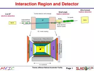
Generic Detector - IR Details Steel Yoke (no yoke for 4th) Antisolenoid Solenoid BeamCal ECal HCal Low Z Mask TPC or Si Tracker FD Cryostats Detectors Working progress John Amann, et al LumiCal Vertex Detector IP Chamber Global Design Effort
Generic IR layout Vertex Detector Mask Beam Cal QD0 Space for Feedback Kicker IP Chamber OC0 LumiCal Detectors SD0 FD Cryostat Group 1 Valves for Push Pull QF1 QDEX1 SF1 OC1 Warm Beam Pipes FD Cryostat Group 2 QFEX2 Global Design Effort
IR forward region and chambers • Watch in study & design: • integration; support; assembly; wake-fields and EMI; location of BPMs; vacuum & pumping; cold-warm transitions; etc. Global Design Effort
Shielding the IR hall 250mSv/h Self-shielding of GLD Shielding the “4th“ with walls Global Design Effort
Working progress on IR design… Mobile Shield Wall Illustration of ongoing work… Designs are tentative & evolving Structural Rib 3m Thickness Overlapping Rib Mobile Platform 20m x 30m Electronics/Cryo Shack 1m Shielded 25m Height 9m Base John Amann Global Design Effort
Beamline shielding Pac Man Open Illustration of ongoing work… Designs are tentative & evolving Recessed Niche Pac Man Closed Beam Line Support Here John Amann Global Design Effort
Beamline shielding CMS shield opened Looking into experience of existing machines… pacman opened SLD pacman closed pacman opened door tunnel pacman closed Global Design Effort
Air-pads at CMS • Single air-pad capacity ~385tons • Air-pads equipped with hydraulic jack for height adjustment & service • Lift is ~8mm for 385t units • Steel plates (~4cm) on the floor (compressed air 50bars) • Inclination of ~1% of LHC hall floor is not a problem • Last 10cm of motion on grease pads • [Alain Herve, et al.] Photo from the talk by Y.Sugimoto, http://ilcphys.kek.jp/meeting/lcdds/archives/2006-10-03/ 14kton ILC detector would require ~36 such air-pads Global Design Effort
Displacement, modeling Idealized models Short range deformation (~0.1mm) is very similar in both models. Long range (1/r) deformation (~0.3mm) is not seen in ANSYS because too thin slab in the model More details (3d shape of the hall, steel plates on the floor, etc.) to be included. Long term settlement, inelastic motion, etc., are to be considered. Parameters: M=14000 ton; R=0.75m (radius of air-pad); E=3e9 kg/m^2, n=0.15 (as for concrete); Number of air-pads=36 Analytic model, half-space ANSYS model J.Amann, http://ilcagenda.cern.ch/conferenceDisplay.py?confId=1225 Global Design Effort
Hilman rollers is also a possibility • For pre-determined path of motion for detector exchange, Hilman rollers may be suitable • Standard capacity to 1kton • While not standard items, the 5kton capacity rollers have been manufactured • Durability is important and to be studied Contact Roll Roller Chain Links 5000 ton module will have 51 contact rolls in 3 rows of 17 Global Design Effort
Other considerations Hydraulic Jacks/Shims • Hydraulic jacks for adjustment • Drive systems • Guiding mechanism • Alignment, etc Screw type drive system Global Design Effort
Detector support • Detector may have a supporting platform • size of IR hall increased to allow for this Global Design Effort
Concept of IR hall with two detectors detector B The concept is evolving and details being worked out may be accessible during run detector A accessible during run Platform for electronic and services (~10*8*8m). Shielded (~0.5m of concrete) from five sides. Moves with detector. Also provide vibration isolation. Global Design Effort
Concept of detector connections detector service platform or mounted on detector detector low V DC for electronics high V AC 4K LHe for solenoids low V PS high I PS electronic racks 4K cryo-system 2K cryo-system gas system 2K LHe for FD high P room T He supply & return sub-detectors solenoid antisolenoid FD high I DC for solenoids chilled water for electronics high I DC for FD gas for TPC fiber data I/O electronics I/O fixed connections long flexible connections move together Global Design Effort