Download
1 / 102
1.11k likes | 1.36k Views
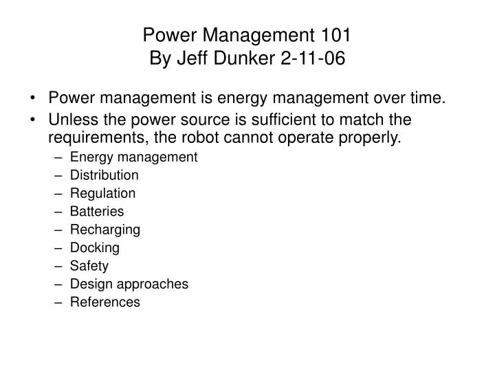
Power Management 101 By Jeff Dunker 2-11-06. Power management is energy management over time. Unless the power source is sufficient to match the requirements, the robot cannot operate properly. Energy management Distribution Regulation Batteries Recharging Docking Safety

E N D
Power Management 101By Jeff Dunker 2-11-06 • Power management is energy management over time. • Unless the power source is sufficient to match the requirements, the robot cannot operate properly. • Energy management • Distribution • Regulation • Batteries • Recharging • Docking • Safety • Design approaches • References
Energy Management • Potential energy • PE = m g h, for a vertical change. Where PE is the potential energy in joules, m is the mass in Kilograms, g is the gravitational acceleration meter/second2, h is height gained meters • Weight – sum of all components • Low weight versus strength trade • Kinetic energy • KE = mv2/2, for a change is horizontal motion. Where KE is the kinetic energy in joules, m is the mass in Kilograms; v is the velocity in meter per second losses in motion is friction • Locomotion methods • Forces needed to move – F = ma • Friction both static and dynamic (kinetic) • F= usmg & F = ukmg • Required speed - v = vo+at • Mechanics – linkages • Reliability and efficiencies
Energy Management • Chemical • Batteries • Thermal • Heat lost by electronics & friction • Components temperatures • Electromagnetic • General electronics issues and noise • Energy recovery • Regenerative braking • Action delegation • Doing it in H/W usually means increased weight and power some solutions but may be cost effective. May be easier to solve in H/W. • Doing it in S/W means a faster CPU may be needed, which could also drive weight and power needs but will increase cost
Power switching & Regulation • Power off sub-components when not needed • Use lower power devices • Run at lower speed • Run at lower voltage • Staged sequence usage
Power off sub-components when not needed • You can tame your usual microcontroller, regulators, and other power-hungry components into a micro power application, if the design permits the circuit to be turned off (or put into a low-current standby state) most of the time, and only occasionally run at full current. • If the switched components run at less than 5mA or so, you can power them directly from a CMOS logic output. The HC/HCT families can supply 5mA with only a 0.5 voltage drop below the positive rail; for higher current, several outputs can be used in parallel. The AC/ACT CMOS families are good for 24mA. • Use a power transistor, operating as a saturated switch (not a follower) to minimize forward drop (thus PNP for a positive supply). The necessary base drive, chosen conservatively large to guarantee saturation, is a disadvantage, though it will probably be smaller than the current used by the switched circuit.
Power off sub-components when not needed(Cont) • Many of the low-power regulators include a “shutdown” input, with very low quiescent current in the standby mode. You can do a power switching by commanding such a regulator into the active state. • Use a mechanical relay, perhaps a latching relay. There’s a good variety now available in DIP’s and tiny metal cans, and they offer zero voltage drop, high overload capability, and the ability to switch bipolarity (or even AC) voltages. In addition, latching relays require no holding current. Be sure to use a diode to protect the relay driver from inductive spikes.
Use lower power devices • Micro regulators • Micro power regulators IC’s with micro-amp quiescent currents capable of substantial output currents are now more available. Including any Negative supplies. • Ground reference • Most op-amp circuits use symmetrical power supplies, usually +/-15Volts, because of the flexibility of dealing with signals near ground. A single supply op-amp can be made by generating a reference voltage that substitutes for the ground reference voltage. Note the reference voltage doesn’t have to be half of the battery voltage; it may be best to split the supply unsymmetrical, to allow maximum signal swing. The ground reference must present a low impedance, both ac and dc and at signal frequencies. • Micro power • Op-amps, Low power comparators, Low power timers & oscillators can all be used to bring the analog components power requirements down. • Low power digital • For micro power digital look into the 4000B/74C series and the 74C and 74AC series, as well as the 74HCT and 74ACT series
Current limiting It is essential to limit the inrush current on power-switched circuits, for two reasons; • The high peak current that would result from switching a battery (bypassed with a capacitor) into a load (similarly bypassed) could destroy the switch; this is true even for a small mechanical relay, which is most likely to fail by having its contacts fuse shut. • Furthermore, the momentary collapse of the battery voltage during a high current-switching transient can cause volatile memory and other circuitry being held in a standby state to lose information. • As long as the switch can handle the transient, you can decouple the negative going dip from the maintaining regulators with a diode (A) • You can do the switching upstream of a current-limited regulator (keep its input bypass capacitor small) (B) • You can put the switch after the regulator. This isn’t as good because of degraded supply stiffness due to the switch’s R on (C). • You can use upstream current-limited switching (D)
Recharging • Chargers • Inexpensive chargers are little more than an AC to DC transformers and may have little to no voltage or current regulation. • Expensive charges can offer the benefit of a dedicated microcontroller addressing the needs of specific cell chemistry. • Smart chargers measure a batteries charge (via voltage – current versus time), no cycles, and temperature. Some even estimate the batteries internal resistance. These devices can be communicated with for the microcontroller to act on the information • Self made design can use custom IC that are offered by several makers, Linear Technology, Maxim, Texas Instruments, National Semiconductor are a couple.
Distribution • Frame • You will want to secure the battery to the frame low on your robot to keep the center of gravity low. You don’t want to have it moving your CG and performance around or worst yet banging in to other parts and possible damage them. When securing them remember you are going to need to service the robot at some time. Battery don’t last forever, this is very important if you don’t charge them on the robot itself. Don’t pot the cells as this will block the vents on them and can lead to an explosive even.
Distribution (cont) • Wiring • Connectors • Always pay attention to the voltage isolation ratings and current handling abilities to avoid failures. • Spring contacts should be resilient in order to take up dimensional tolerances between cells. Single point contacts are adequate for low current loads, but you should consider multiple contacts for higher current loads. Remember batteries are heavy and in an environment of severe vibration or shock they will probably need extra anchorage a shock absorption material. • Don’t forget they add resistance at each point and worst yet their resistance varies as a function of temperature, vibration and moisture. So make as few connections as possible. • Vibration - use connectors that lock together, you don’t want your robot to be in a contest at the moment of victory to have a connected come loose and lose. • In general it can be said that soldering is better than crimped which is better than a mechanical connection.
Grounding • The cures for a ground loop are • Open the loop by grounding only at one point • Reduce the area of the loop • Reduce the flux normal to the loop • Reduce the flux by adding EMF shielding
When ground isn’t ground anymore I2 10mA I3 10mA I1 20mA Power supply connection 0 V rail A B C D It = I1+I2+I3 • Assume the 0 Volt conductor has a resistance of 10 milli ohms per inch and • that points A, B, C and D are each one inch apart. The voltages at points A, • B, and C referred to D are: • Vc = (I1 + I2 + I3) * 10m ohm = 400 uV ( see below => 0.1 V ) • Vb = Vc + (I1 + I2) * 10m ohm = 700 uV ( see below => 0.2 V ) • Vc = Vb + I1 * 10m ohm = 900 uV ( see below => 0.3 V ) • This is typical but becomes a problem and can cause circuits to oscillate when: • When currents become Amps instead of mA or uA, IE Let I1 = 10 Amps • When the conductor impedance is in ohms not milli ohms, R = .1 and I1 = 1A • Where the voltage drop, is sufficient to affect another circuits operation.
Small signals and noise • Sensors on the robot may present a very small signal in a high noise environment. Usually, the signal is located some distance from the amplifier. As a consequence, a large amount of noise and hum is often introduced. Effective signal recovery often depends on carefully choosing the optimum amplifier for a particular application. There are three common types of systems in use: • Single ended input and output (operational amplifiers) • Some design use shielded cables. These are prone to noise pick up, because the signal is referenced to ground, i.e. the signal flows through the system ground, with noise being added along the way. Resulting in both the signal and noise to be amplified. Typically a filter is used to try to remove the noise component. But the noise can be larger than the signal itself. • Differential input , single ended output (instrumentation amplifiers) • This is a better method for recovering weak signals. The signal is applied between two input lines, with no signal traveling through the ground connection. Since much of the noise is the same on both inputs (common mode) it is rejected by the amplifier, which amplifies only the differential signal. Note: that the inputs of most instrumentation amplifiers require a dc return path (using resistors) for the amplifier’s input bias currents. This is important for ac-coupled, single supply applications where the input common-mode reference and output reference are raised above ground. • Differential input and differential output (differential amplifiers) • These are used in high bandwidth applications, such as ADC’s of buffering DAC’s. It is also used in most medical applications as it provides the required safety.
Chassis ground Chassis ground point Expected return current path Undesired chassis return current • Return current with multiple ground points • Connection should only be made to a conductive (usually metal) chassis at one point • all wires need to be brought to this point. • The purpose of the single-point chassis ground is to prevent circulating currents in • the chassis. If multiple ground points are used, even if there is another return path • for the current to take, a proportion of it will flow in the chassis. Such currents are • very hard to predict and may be affected by changes in construction, so that they • can give unexpected effects: it is not unknown for hours to be devoted to tracking • down an oscillation or interference, only to find it gone after tightening a chassis screw.
Ground loops Induced series EMF Two point grounding Flux linkage normal to loop Induced current No Induced series EMF Single point grounding Flux linkage but No loop Lenz’s law tells us that the EMF induced in the loop is V = -1E-7 * A * n * (2* pi * B *cos(2*pi*f)) Where A is the area of the loop in cm^2 B is the flux density normal to it, in Gauss, assuming a uniform field n is the number of loops Let’s take a 10 Gauss 60Hz field acting through a 10cm^2 single loop We would get 359uV signal induced
Ground Loop POWER LOGIC DEVICES POWER SUPPY ACUATORS GROUND SENSORS WRONG SENSORS
Ground Loop Fixed POWER LOGIC DEVICES POWER SUPPY ACUATORS GROUND SENSORS RIGHT SENSORS
Ground Rail POWER LOGIC DEVICES POWER SUPPY ACUATORS GROUND SENSORS SENSORS BETTER Because it has a single point ground which eliminate the multiple line drop voltage shifts
Power Rails POWER LOGIC DEVICES POWER SUPPY ACUATORS GROUND SENSORS SENSORS BEST What applies to the ground actually applies to any current bearing power rail
Power supply configurations Batteries Motors Electronic logic & sensors Logic power can be buffered from motor transients by a large capacitor or super cap
Power supply configurations Batteries Motors Electronic logic & sensors The diode protects the logic against brief voltage dips when the motor demands high surge currents
Power supply configurations Regulator Analog, switching, or DC-DC Batteries Motors Electronic logic & sensors Using a regulator alleviates different voltage problems and adds a filter against noise
Power supply configurations Batteries Batteries Motors Electronic logic & sensors Having completely separate power supplies makes the Robot bulkier but alleviates noise problems and accommodates different voltages with out additional electronics
Power supply configurations Motor controller Opto Isolator Opto Isolator Batteries Motors Electronic logic & sensors Batteries An Opto isolator can provide complete electrical isolation among different parts of a circuit. There is no electrical connection between logic and power supplies.
Regulation • Need for Regulation • Microcontrollers, op-amps, optical detectors and other circuitry require efficient regulated power sources, and these can be derived from also most any type of battery. However, batteries that work well in smoke detectors and small toys where voltage stability is a secondary concern are not always the best choices. • Multiple voltages • Analog sensors often need bipolar voltages (e.g. +/- 12V) and these can be derived using a separate battery for each voltage required. Another approach is to use a single battery followed by a converter generating both plus and minus voltages, referenced to a common ground. For low power applications this is often more convenient, less expensive, saves weight and reduces battery maintenance.
Regulation (cont) • Metering usage - Gas gauge technology • Smart batteries generally contain a communication device that contain a cycle counter to count the number of charge and discharge cycles, and/or a fuel gauge to track the remaining run time per cycle and report the battery’s state of health. • Voltage based fuel gauging relies on the periodic voltage measurements of the battery pack, and works best on a cell technology with a sloping discharge curve. This method has its limitations, however, since it only estimates relative capacity. • The one-wire method can determine battery capacity by monitoring the amount of current input to, or removed from, a rechargeable battery. The IC monitors a voltage drop across a sense resistor connected in series between the negative battery terminal and ground.
Regulation (cont) • Metering usage - Gas gauge technology • Two-wire, or coulomb counting, is the most accurate method, and allows absolute capacity estimation while giving capacity information during use. The most common protocols for the two wire method are I2C and SMBus. The ICs must be calibrated to ensure they are functioning and communicating properly. • High power and low power circuits • Because motors are notorious for generating EMC fields and line noise separate power sources are often used. Be careful on creating a ground loop otherwise this method will also have problems. Filter capacitors (typically 0.1 uF) close to the motor do help but may not be enough. • When individual electronic portions of a robot test ok but misbehave as a composite unit, use an ac coupled oscilloscope to check for noise on the power rails. It is surprising how much noise can be transferred to power lines by motors, relays, and other high current elements.
Regulation (cont) • High power and low power circuits • Noise generators can be traced by removing suspected elements sequentially while monitoring the power rails. Culprits should be decoupled with 0.1 uF ceramic capacitors placed across the power lines where they enter the noise source, make these leads short and take them directly to ground/common. Using 10 uF Electrolytic or tantalum capacitors in parallel with the 0.1 uF can help drooping affects and can be installed on the power bus keep these leads as short as possible also. If interference persists despite these efforts, separate supplies should be used for noisy equipment. A common ground must usually be provided between all supplies but connect all common leads at ONE point only. Noise is often less problematic when using low internal impedance cells such as lead acid and NiCad, NiMH batteries.
Regulation (cont) • Linear regulators • Linear regulators such as the LM7805, LM317, and LM337 etc. require around a volt or two above the regulated value to operate properly. Since this reduces your effective use capacitive the LDO (low drop) variety can help out. Note that voltage drop and current you are using cause a loss of power at the regulator which turns it all into heat. The most common variety, are cheap but relatively inefficient. In effect they step down voltage from one level to another; the different in voltage is dissipated as heat. This heat can be dealt with; but the real problem is the unnecessary drain on the battery. It’s better to conserve battery power for productive tasks, like running the robot’s motors.
Regulation (cont) • Switching regulators • Step-up and Step-down regulators (MAX631) also switching voltage regulators are more efficient – some offer efficiencies of up to 80% - but they are more expensive to implement, and many require additional components and design consideration. Like linear regulators, switching regulators step down one voltage to provide another. • DC-DC converters are self contained voltage changers. They are the most expensive of the lot, but they require no additional components. DC-DC converters can step down or step up voltages and can provide negative voltages. The disadvantage of many DC-DC converters (besides cost) is that they require high input voltages in order to supply adequate current at the output. For instance, the input voltage may be on the order of 24-28 volts, in order to provide reasonable current at 5 or 12 volts.
Batteries • Battery parameters • Energy density • Capacity • Voltage • Internal resistance • Discharge rate • Shelf life • Temperature dependence • Batteries types & chemistries • Primary cells - Not rechargeable • Secondary cells – Rechargeable • Battery alternatives
Energy density & Capacity Energy density • Ideal – very high • It is the Amp-hours divided by it weight • It is also expressed as a volume calculation then it is Amp-hours/volume Capacity • Ideal – very high • Manufactures assign batteries a “C” rating equal to the batteries energy capacity measured in Amp-Hours (Ah) when discharge at a C/10 rate. They also rate them at optimum freshness. In general the amp-hour rating is done at the 20 Hour rate. Check the manufacture notes because some are using a C/5 rating for their batteries. • A battery with less than 61% of it label voltage needs to be replaced, 62%-72% is weak, 73%-100% is good.
Energy density & Capacity (cont) Capacity • Usually the cell size in increased to increase the capacity of the cell. This works because you have more active region for the chemical reaction to occur. • Another method to get more amp-hour capacity is to put the cells in parallel combinations. This can be done to increase the capacity or discharge capability, or the reliability of the battery. Increased reliability requires a series diode in each parallel path to isolate failed cells. Some battery systems are hazardous if a cell is inserted or connected the wrong way round (they can explode).
Voltage • Ideal – constant or flat • Open circuit voltage is an unreliable measure of remaining capacity. A well drained battery may indicate almost 95% of its full charge voltage if it hasn’t been used for a week or so. Similarly an almost completely discharge battery will have the same voltage as a new battery after only a short charge, though it is dead for all meaning full usefulness. Another way to view this is the open circuit voltage can exceed the voltage under load by up to 15%. • The voltage profile versus run time curve and a given load is a function of the batteries chemistry. The flatter this profile is, the better.
Voltage (cont) • Series combination of cells is used to get higher voltage than what an individual cell can provide. Note this also decreases the reliability of the overall package, and there is a risk of the weakest cell being driven into reverse voltage at the end of its life. This increases the likelihood of leakage or rupture, and is the reason why manufactures recommend that all cells be replaced at the same time. Good design practice will minimize the number of series-connected cells. There are now several ICs which can be used to efficiently multiply the voltage output of even a single cell.
Model of Battery High ~100Meg Ohms It is this resistance that determines shelf life ~0.01 Ohms This resistance determines the Discharge rate and efficiency 1.2 Cell voltages
Internal resistance & Discharge rate Internal Resistance • Ideal – very low • A battery’s resistance becomes more important when it’s going to support high current for a short time. With most primary batteries the internal resistance increases with storage time, use, and low temperatures. • After a 100 cycles the impedance can double on some batteries. Discharge rate • Ideal – capable of rapid discharge, Surge peak currents, & Steady loads • Avoid shorting out the terminal of a battery as it can damage them
Shelf life • Ideal – unlimited • The self life of the battery is very much a function of the ambient temperature. A battery stored in a cold location will do much better than one stored in a hot location. • Most chemical reactions go more slowly as the temperature drops, and at low temperatures a battery’s shelf life due to self discharge can be extended considerably. • Avoid storing batteries in temperatures above 75 – 80 degree F. A battery above 100-125 degrees F causes rapid deterioration. • Note: • Improper charging will reduce a battery life. • Deep discharging of most batteries usually reduces it life.
Temperature dependence • Ideal – very insensitive, wide range • General purpose batteries are designed to work at 70 degrees F any deviation from this temperature changes the performance called out by the manufacture. • The battery temperature increasing while discharging. • Service life decreases at low temperatures because chemical activity in the battery’s cell decreases. This low temperature effect is more predominate at high current drains. Terminal voltage also decreases as temperature decreases. Remember that the battery open circuit voltage is more that a closed circuits voltage.
Batteries types & chemistries • Although many types of batteries (Duracell list 133 off-the shelf types) are sold, only a few are suitable for robotics because of cost, availability, voltage, and current capability. Avoid hard to get batteries. Select the cell type as early as possible in the robot design for both the electrical and mechanical properties. • Unlike capacitors, batteries do not store electrical charge; they generate electric current through chemical reactions. Once these chemicals are depleted, the battery is dead. The main difference between the chemistry of a primary battery and a secondary battery is that the chemical reaction is easily reversed while the primary is not.