Download
1 / 17
170 likes | 371 Views
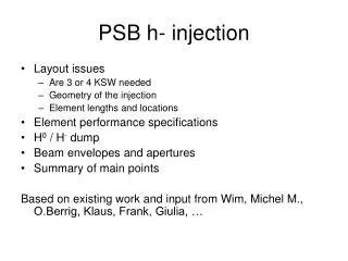
H - Beam Injection @ SNS. B. Mikulec 16/12/ 2013. Injection Principle. First stripping foil converts ~98% of H - to p H - injection allows injecting into the same phase-space area by merging H - and circulating p beam with zero relative angle Small transverse emittances can be achieved

E N D
H- Beam Injection @ SNS B. Mikulec 16/12/2013
Injection Principle • First stripping foil converts ~98% of H- to p • H- injection allows injecting into the same phase-space area by merging H- and circulating p beam with zero relative angle • Small transverse emittancescan be achieved • At SNS: second thicker stripping foil to convert waste beam to protons and dump waste beam + beam missing first foil in a dedicated beam line S. Cousineau: Ring Injection and Collimation Systems; SNS training pages
SNS Injection Constraints • Closed orbit bump of ~100 mm • Merge H- and circulating p beam with zero angle • Foil placed in 2.5 kG field of magnet#2; peak field of magnet#3 has to be <2.4 kG to avoid stripping of H0 excited states in #3 (losses!) • Field tilt in magnet#2 [arctan(By/Bz)]>65 mradto remove the electrons off the foil and collect them on electron catcher at bottom of vacuum pipe (545 keV and ~1 kW of power @ 1 GeV and 1 MW) • Need to dump H0 and H- beam with minimal losses on injection dump M. Plum: SNS Injection and Extraction Systems – Issues and Solutions, Proc. of Hadron Beam 2008, Nashville, Tennessee, WGC04
Primary Stripping Foil SNS • Primary stripper foil: diamond film grown on Si substrate; 0.3 mg/cm2 • Due to thermal expansion mismatch Si – diamond: developed a corrugation method through a patterning process to avoid the foils scrolling up after release from substrate • After beam power ramp-up in 2009 many foil breakages • Forced to run at lower beam power during ~4 months
Potential Causes of Foil Failures • Arcing due to charge build up on the stripper foils • Secondary electron emission and/or thermionic electron emission leaving foil positively charged • Foil needs to be well grounded! (bracket and clamp machined flat; Si substrate sandwiched between Au or Cu foils + conductive glue) • Emitted electrons hitting the foil bracket • Reflected convoy e- • Electron catcher not anymore at correct position + alignment wrtfoil • e- from trailing edge multipacting (Al coating of vacuum chamber maybe not ideal!) • Beam halo hitting Si substrate or bracket • Beam excursions • Eddy current heating • Foils get too hot during operation • …
Cures + other Foil Issues • Modified foil brackets (Ti and new mechanical design) and foil position (+1 cm); longer and wider foils; stainless steel washer on chain saw pin; improved electrical contact • Other foil materials on test: HBC (hybrid boron carbon); used at JPARC; better conductivity • Other observations: • Foil shaking: • Beam appears to be moving, but it doesn’t (only angle to camera) • Some beam can miss the foil intensity fluctuations visible from beam on dump • Also observed with DC current and HBC foil • Shaking sometimes reduces when moving slightly the beam (structural?) • Bright spots (glow visible even after beam passage): • Outgassing of foil and fluorescence?
Foil Exchange Unit • dfa S. Cousineau: Ring Injection and Collimation Systems; SNS training pages
Foil Exchange • Last foil failure in April 2012 • Preventive foil exchange at beginning of each ~5-monthly run cycle and during every multi-day MD period (every 4-6 weeks) • Conditioning of foils after exchange: • Ramp up to 400 kW in 1 hour and then slow increase of max. 40 kW/h • Step-wise increase of duty cycle to slowly warm up foil • Sometimes move foil up/down/left/right for more efficient outgassing • Takes almost a day (start already towards end of MD) • Slow stripping efficiency degradation never reason for foil exchange at SNS (rather mechanical, distortions, foil shaking) • Most issues seem to be related to 60 Hz operation; 1 Hz might not be problematic
Early Problems with Injection Section • Chicane bump was not functioning correctly due to design changes to magnets #2 and #3 ( poor ring injection and waste beam transmission) and some unforeseen issues • Adjustment of magnetic field, but compromise was needed only one waste beam type could be transported correctly to dump • Width increase of secondary stripping foil for wider range of chicane settings and full interception of H- beam • Installation of C-shaped magnet for independent horizontal steering of the 2 waste beams • Installation of additional beam instrumentation behind C-magnet • Thinner secondary 3.2 mg/cm2 polycrystalline graphite foil to reduce losses due to scattering (was 25 mg/cm2 carbon-carbon) • Shift of magnet #4 by 8 cm so that H- still pass in good field region to avoid losses due to vertical deflection • Enlarge vertical gap of septum magnet and modify vacuum chamber
Beam Loss in Injection Dump Line • Stated to be the main performance limitation of injection section (M. Plum) • Dump: copper plates with interleaved water cooling; ~84 cm long (rated for 150 kW); 8 interlocked inorganic thermocouples in the beam halo • Key BLM locations marked with red ellipses…; all interlocked
Transverse Painting • Contrary to the PSB: horizontal AND vertical phase-space painting to reduce peak beam density (2x4 kickers)
Painting Bump • Time-dependent bump with kicker magnets
Control of Painting Bump • Start at max. height circulating beam close to foil • Followed by a turn-by-turn decaying waveform p beam moves away from foil Additional timings allow additional control of Tb (delay, accumulation time, storage time)
Beam Instrumentation in Injection Section • Many BLMs! • Fast BLMs at both foil locations • Screens • Infrared camera to view beam on foil • Video camera for foil movement • BCTs and BPMs in dump line • Time of flight in dump line • Wire scanner in dump line • Thermocouples on dump
Lessons • Design in lots of tuning flexibility in case of unforeseen issues • Sufficient and redundant beam instrumentation • Careful 3-D field simulations and tracking; determination of higher order multipoles for wide enough tuning range • The smallest detail can become a problem well-thought design! • (Independent control over multiple beams; H0, H-, p) • Easier at PSB: • Low duty factor (foil issues!) • Lower injection energy (losses less critical) • More difficult at PSB: • Beam brightness requirements!!! • Different adjustment required for our ‘cycle zoo’! • 4-ring compact design and no external dump line • Longitudinal painting