Download
1 / 26
260 likes | 268 Views
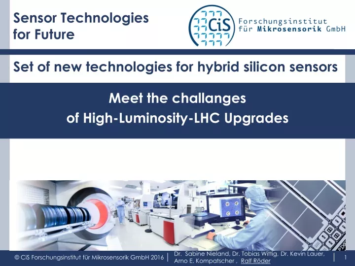
Sensor Technologies for Future. Set of new technologies for hybrid silicon sensors. Meet the challanges of High-Luminosity-LHC Upgrades. Dr. Sabine Nieland, Dr. Tobias Wittig, Dr. Kevin Lauer, Arno E. Kompatscher , Ralf Röder. Outline. Wafer Defect engineering

E N D
Sensor Technologies for Future Set of new technologies for hybrid silicon sensors Meet the challanges of High-Luminosity-LHC Upgrades Dr. Sabine Nieland, Dr. Tobias Wittig, Dr. Kevin Lauer, Arno E. Kompatscher , Ralf Röder
Outline Wafer Defect engineering • New material # bonded wafers • Detector Devices • Chip edges • Biasing • Under-Bump-Metallization • Module Soldering • Mounting & Assembly Ongoing Activities at CiS RD50 Workshop, Turin, Italy June 2016
CiS R&D and industrial services Design Wafer processing Assembly Test & Analysis 3D technology modules: Si membranes TSV … MEMS preasuresensors cantilever microchannels # Lab-on-Chip Harshenvironment High temperature Impedansetemperaturesensors MEOMS UV … IR oesystems Silicon Detectors HEPHybrid Modules Industrial Use RD OEC SiPM Reliability Analysing methods Defect engineering Assembly UBM, bumping, soldering RD50 Workshop, Turin, Italy June 2016
CiS CLAIM: Development of cost effective technologies and products Requirementsfromour(industrial) customers : Costefficienttechnologysets: Wafer + back-end processing # reliability # stability + test # testability + assembly # reliability optimization have to cover the complete process flow Our focus is to coordinate the technologies in order to cope with the application challenges on the one side and the cost efficiency on the other side. RD50 Workshop, Turin, Italy June 2016
Wafer Defectengineering • DOFZ vs. Nitrogen enriched crystalFZ Si:N • pad-detectors (diodes) forTopsil / ITME „NitroSil“ • in parallel / addition: 3 FZ Si:N+ DOFZ + CZ • measurementsbeforeirradiation IV, Voc(t) • at presentirradiation1MeV e- andprotons 5x10¹³-5x10¹⁵neq cm-2 • next: FTIR, … • Dependency of ASi-Sii-defect density on [Oi]2 Thermal donor generation rate depends on [Oi]2 as well. Lauer et al., AIP Advances 5, 017101 (2015). RD50 Workshop, Turin, Italy June 2016
Defect engineering Measurement setup WT2000 MWPCD Microwave detected photoconductance decay setup from Semilab Equipped with hot plate Illumination of sample by excitation laser Carrier lifetime extracted at fixed excess carrier density Δn = 5x1014 cm-3 [1] hotplate [1] K. Lauer et al., J. Appl. Phys. 104, 104503 (2008). RD50 Workshop, Turin, Italy June 2016
Testing, analytics and calibration Climate test chambers control of temperature and humidity Additional to the standard program are simulators which enable a nearly complete environmental simulation. Temperatureshockchamber Pressurecooker Semi-automatic eight-inch wafer samplerfour/six-inch double-sided wafer sampler Semiconductor metrology (CV, TVS, UBR, pinhole, lifetime) Solid state analytics (REM, EDX, SIMS, AFM, optical profilometry) SIREX FIB RD50 Workshop, Turin, Italy June 2016
Defect engineering Analysis methods nowavailableCryostat 3,5 … 350 K closedcyclecooling He system: > 100 mW bei 4 Ktemperaturestability: < 10 mK pp max. sample size: 25 mm x 25 mm x 5 mmwindow: Ø 30 mm, availablewindowmaterials: ZnSe, quartz, Polyethylene (2 mm thick) FTIRandDLTS WT2000 Life time Microwave detected photoconductance decay (MWPCD) MWPCD decay time accordingtothestandard(SEMI PV9-1110) Irradiation degrades samples very strongly. Low temperaturephotoluminescence PL spectroscopy Phenomenon of light-induced degradation (LID) BSi-Sii-defect, ASi-Sii-defect @1MeV e- @ Protonen 5x10¹³-5x10¹⁵neq cm-2 RD50 Workshop, Turin, Italy June 2016
More new analysis methods SIREX and FIB Visualized stress in a wafer SIREX Device Stress Imaging System polarized light measures the depolarization to by two highly sensitive analyzers in reflective mode:using a very high focusedpolarized laser beam today it is difficult to interpret the results advanced software will install in a few months investigation of 3D structures RD50 Workshop, Turin, Italy June 2016
Analysis AURIGA 60 CrossBeam Workstation from Carl Zeiss: Resolution Slicing and 3D-Imaging with Unrivaled Variety of Analytical Options Features: • In-lens SE, ETD, EsB, 4QBSD, SESI • STEM detector • EDAX EDX+EBSD detector • Omniprobe 400 • GIS for C, Pt, W and Si • Gallium Ion Optics RD50 Workshop, Turin, Italy June 2016
Wafer New material # bonded wafers Large area thinning: integrated in process flow in progress transfer from 4inch to 6inch Double sided processing of thin wafers ( 150 µm) Silicon fusion bonded wafer stacks before wafer processing high temperature bonding FZ + FZ wafers high-ohmic FZ + CZ (low-ohmic) wafers high-ohmic FZ + CZ (lowest-ohmic) wafersoption: + LAT after wafer processing, especially for thick detectors pc Diamond layer RD50 Workshop, Turin, Italy June 2016
Devices: Focus HEP and CR double sided processed pixel and microstrip detectors pixel sensors, especially FE-I4 quadsfor new generation of hybrid detector modules reduced chip edge # reduced chip edge demage ICP etchedchipedges & sidewall doping in process thinning down to 100 µm new biasing concepts # new test concepts removeable bias rails large aera thinned detectors (LAT) double metal one front side Particle detectors (very) thin detectors (photodiode, pixel, ...): 10 ... 100 ... 150 µm thicker detectors > 700 µm thin dead layer for alpha detectors RD50 Workshop, Turin, Italy June 2016
Large area thin detector prototype run with MPP n-in-p ATLAS pixelsensors FE-I4 Quad-Sensors (~4●4cm²) + SCS FZ p/Boron, <100>, > 10 kΩcm, (525 ± 25)µm targetthicknesses 100 µmand150 µm large areacavityetching KOH anisotropicetching nomechanicalbreakage relativelysmallthicknessfluctuationsin theorderof ~10µm smallscale (AFM measurements)averagefluctuations in theorderof a few 10nm RD50 Workshop, Turin, Italy June 2016
Large area thin detector prototype run with MPP Under-Bump-Metalization 4 Wafer Lift-off-mask + Ti (~10 nm sputtered) 20 nm Ti + 200 nm Ni + 20 nm Au MPP: Americium source scans of the SCM modulesproduced with the 4" CIS production with backside etching and Nickel UBM: mostly good interconnection efficiency observed (besides a very bad one, except a few pixels in some corners) 6 Wafer 30nm Ti, 200nm Pt, 100nm Au 6 Wafer still waiting for IZM-UBM(wafer support / handling not solved) Dr. Anna Macchiolo, Max-Planck-Institut für Physik RD50 Workshop, Turin, Italy June 2016
Large area thin detector prototype run with CERN: Thin „EPI“ sensors n-in-p sensorswithpolycrystallinesiliconresistors microstrips(80µm pitch, Poly-Si-Res) diodes(twosizes), spaghettidiodes „Epi“ (525µm bulk + 50µm epi): etchingthecompletesubstrat ITME waferwithepiresistivity: 10 Ωcm 50 µm thickactivearea: 17 pcsmschipsdiced 50 Ωcm 50 µm thickactivearea: 10 pcsmschipsdiced 250 Ωcm 50 µm thickactivearea: 21 pcsmschipsdiced 1000 Ωcm 50 µm thickactivearea: 25 pcsmschipsdiced 100 µm thickactivearea: 6 pcsmschipsdiced RD50 Workshop, Turin, Italy June 2016
Large area thin detector prototype run with CERN: thin FZ sensors n-in-p sensorswithpolycrystallinesiliconresistors Bulk type (285µm: etchingto 50, 100, 150, 200 µm (+unetched): backsidepartiallycavityetching p/BoronCZ (Siltronix) bulkresistivity100 Ωcm, waferthickness 350 µm 1 pcwafer 50 µm thickactivearea 1 pcwafer100 µm thickactivearea 2 pcwafer150 µm thickactivearea p/BoronMCZ (Okmetic) bulkresistivity> 2000 Ωcmwaferthickness300 µm 2 pcwafer 50 µm thickactivearea 2 pcwafer 100 µm thickactivearea 2 pcwafer 150 µm thickactivearea 1 pcwafer200 µm thickactivearea p/BoronFZ (Topsil) bulkresistivity> 2000 Ωcm waferthickness285µm 2 pcwafer 100 µm thickactivearea 3 pcwafer 150 µm thickactivearea 2 pcwafer200 µm thickactivearea Active area thickness 100 µm RD50 Workshop, Turin, Italy June 2016
Large area thin detector 6inch prototype run • n-in-p ATLAS pixelsensors FE-I4 Quad-Sensors (~4●4cm²) + SCSadditionallyseveralothernewdesigns • RD53 testchip50x50 and 100x25µm² pixelsize • CMS Roc4Sens 50x50 and 100x25µm² pixelsize • Omegapix • Medipix • p/Boron FZ: <100>, > 3 kΩcm, (350 ± 20)µm, 300 nm dry oxid TTV < 10 µm, Bow < 30 µm, Warp < 30 µm • processingstarted • targetthicknesses 100 µm and150 µm • large areacavityetching • KOH anisotropicetching bias grid variation RD50 Workshop, Turin, Italy June 2016
Edge Less Detectors Active Edges reductionofinactivesensoredgebydopingofsidewalls severalparametersarevariedwhichcanbecompared p- and n-type bulk sensorthickness (300 & 100µm) threeside wall dopingmethods trench widths numerousedgedesignshadbeensimulated most promising oneswereimplemented in thelayout sideimplantation in progress RD50 Workshop, Turin, Italy June 2016
Bias grid design and technogies • Collaboration with MPP • see talks: Clara Nellist LAL • new inhouse project: A.E, Kompatscher • Solutions • Lift-off mask • Fuses RD50 Workshop, Turin, Italy June 2016
“Stacked” detectors Diode wafer run with SFB wafers Idea: investigateinfluenceof SFB interfacesofdiodebehavior, especiallyofthedefects Devices same as in first CiS – Hamburg projects and Nitrosil: SDFTW01-pad-diodes First small run: 6 pairs of two 285 ... 300 µm thick dspw estimated process end: October 2016 Second run is planned for 2017, based on first experience RD50 Workshop, Turin, Italy June 2016
Additional Detector activities • SiliconPhotomultipier • Secondwafer run: epi wafer run • various cell designs • various chip designs • Single Photon Counter • APD • SiC diodes • CiS R/O chips processed by X-FAB RD50 Workshop, Turin, Italy June 2016
Under bump metalization Bump deposition or soldering History: CMS Pixel @ PSI: CiS UBM Ti+Ti/Ni/Au structured using lift-off mas PSI: deposition of In-bump Mask based processes: Lift-off mask on chip Stencil printing Silicon transfer master (filled etched cavities) Electroplating or mask-less & electro-less (wet chemical) various materials: Ti, Ni, Cu, Pd, Pt, Ag, Au … available + solder, filled adhesives et al Under development with local partner: copper pillars 5 … 20 µm (pitch ~ < 10 µm possible) Light induced plating ongoing: feasibility studies cost vs. technology, esp. comparison of soldering alternatives
Under bump metalization Bump deposition or soldering Introduction of light induced plating vs. electrolessNi UBM Rehman /Lee: Materials 7(2014)2 p. 1318 ff Sn 1-2 µm Cu Ni Seed layer Si solderable, but no solder tin = solderable and solder RD50 Workshop, Turin, Italy June 2016
Module Module Soldering Mounting & Assembly Assembly: chipbonding, wire-bonding Au studbumping flipchipassembly (adhesiveor thermal compressionbonding) Micro AssemblyPlatform „OurPlantX3BLUE“fromHaeckerautomation: newuniquetoolfor microassembly (fineplaceandprecisebonding), microdispencingandlasersoldering from prototype development to mass production. Optional additional features: Micro channelcooling integrated in siliconinterposer Silicon large areaplateswithmicrochannels RD50 Workshop, Turin, Italy June 2016
Summary & Outlook We can offer various technologies and capabilities to develop new devices + detector chips + modules. Thank you for attention! RD50 Workshop, Turin, Italy June 2016
Analysis • PHYWE XR 4.0 expert unit RD50 Workshop, Turin, Italy June 2016