Download
1 / 21
210 likes | 376 Views
The adaptive secondary mirror for the 6.5 conversion of the MMT. Presented by A. Riccardi. A. Riccardi 1 , G. Brusa 1 , C. Del Vecchio 1 , R. Biasi 2 , M. Andrighettoni 2 , D. Gallieni 3 , F. Zocchi 4 , M. Lloyd-Hart 5 , F. Wildi 5 , H. M. Martin 5.

E N D
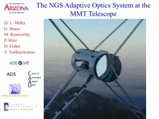
The adaptive secondary mirror for the 6.5 conversion of the MMT Presented by A. Riccardi A. Riccardi1, G. Brusa1, C. Del Vecchio1, R. Biasi2, M. Andrighettoni2, D. Gallieni3, F. Zocchi4, M. Lloyd-Hart5, F. Wildi5, H. M. Martin5 1 – Osservatorio Astrofisico di Arcetri, Firenze, Italy 2 – Microgate, Bolzano, Italy 3 – ADS, Lecco, Italy 4 – Media Lario, Lecco, Italy 5 – Steward Observatory, Tucson, AZ, U.S.A.
People (some of them) Osservatorio di Arcetri
Adaptive Secondary Concept Adaptive Secondary Adaptive Secondary Conventional Secondary WFS Sci. Camera Less warm surfaces WFS BS K band: 2-2.6 shorter exp. time (MLH, PASP) TTM DM Coll. Sci. Camera
Large stroke, no hysteresis P36 prototype 240mm 36 act. prototype (l=633nm) Astigmatism PtV=12mm
System Layout • mirror diameter 642 mm • mirror thickness 2 mm • membrane in-plane restraint • 336 moving magnet • actuators • nominal air gap ~ 40 mm • reference body 50 mm thick • AL cold plate: actuators support & cooling (7 cooling channels) • 24 absolute gap sensors • fixed hexapod • support frame & interface to Hexapod • electronics cooled crates • hub interfaces (power, signal & cooling)
Assembled unit Cap. sensor armatures (ref.plate) MMT336 ASPHERIC SHELL 642mm diam. 2mm thick Magnets (12mm diam)
Electronics – control system • 3 crates • 14 control boards each crate • 8 channels controlled by each board (4DSP) • capacitive sensor signal conditioning on the actuators (close to variable gap capacitor)
Resonances in control bw 115mm gap 37mm gap 115mm gap 37mm gap increasing Damping: larger PM P30 “astigmatism” mode TF First 270 modes have nres< 1kHz + local control Phase lag of 180deg for n>nres if low damping => unstable High damping (18Ns/m => 40mm gap) + local control PD
Control loop Feed-forward + + + Commands from WFC @625Hz + - k-th Curr. Driver + coil 40kHz local loop -3dB@56kHz DM Capsens Linearization DSP DSP of k-th channel
Feed-forward matrix - zonal FF matrix (Cap. sensor readings)
Feed-forward matrix - modal Modal excitation: improved SNR (Cap. sensor readings)
Modal stiffness Act stiffness 0.2N/mm FF dominates Local ctrl dominates
Step response Position Command Only Prop. - Gain=0.2N/mm (40mm gap) Settling time 1.5ms
Step response Ctrl+FF Force FF Force
Less Bandwidth wrt P36 P36 MMT336 G=0.2M/mm S.T.=1.5ms G=0.8M/mm S.T.=0.7ms 2mm 7.5mm Less damping, but better static control of the edge
Turbulence compensation nm r0=15cm @ l=550nm, v=6m/s, 8sec nm Residual of first 200 mode Correction (scale X10) Input turbulence 2.3mm rms 140nm rms on acts. Max 0.4N rms (|DT|<1.2 C) (Cap. sensor readings)
Modal analysis (Cap. sensor readings)
Conclusions • The control gain achieved is high enough to ensure proper tracking and correction of atmospheric turbulence. • The unit is now on the optical-test tower at the Mirror Lab for optical characterization • Work is now in progress to optically flatten the mirror and calibrate the capacitive sensors • According to the current schedule we plan to close the optical loop at the optical-test tower in June