Download
1 / 61
610 likes | 778 Views
CCAST. Micromegas TPC. P. Colas, Saclay Lectures at the TPC school, Tsinghua University, Beijing, January 7-11, 2008. OUTLINE. PART I – operation and properties. TPC, drift and amplification Micromegas principle of operation Micromegas properties

E N D
CCAST Micromegas TPC P. Colas, Saclay Lectures at the TPC school, Tsinghua University, Beijing, January 7-11, 2008
OUTLINE PART I – operation and properties TPC, drift and amplification Micromegas principle of operation Micromegas properties Gain stability and uniformity, optimal gap Energy resolution Electron collection efficiency and transparency Ion feedback suppression Micromegas manufacturing meshes and pillars InGrid “bulk” technology Resistive anode Micromegas Digital TPC P. Colas - Micromegas TPC
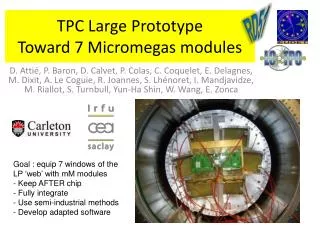
OUTLINE PART II – Micromegas experiments The COMPASS experiment The CAST experiment The KABES beam spectrometer The T2K ND-280 TPC The Large Prototype for the ILC Micromegas neutron detectors TPCs for Dark Matter search and neutrino studies P. Colas - Micromegas TPC
Electrons in gases : drift, ionization and avalanche Typical (thermic) energy of an electron in a gas: 0.04 eV Low enough electric field (<1kV/cm) : collisions with gas atoms limit the electron velocity to vdrift = f(E) (effective friction force) At higher fields ionization takes place (gain 10 V in 2mm =50kV/cm) E Mean free path l=ns (0.4 mm at 1eV) magboltz P. Colas - Micromegas TPC
Cross-sections of most common quenchers follow the same kind of shape, but not all (noticeably, not He); Dip due to Ramsauer effect (interf. when e-wavelength~mol.size) Note : attachment P. Colas - Micromegas TPC
Electrons in gases : drift, ionization and avalanche Thanks to the Ramsauer effect, there is a maximum drift velocity at low drift field : important for a TPC, to have a homogeneous time to z relation Typical drift velocities : 5 cm/ms (or 50 mm/ns) Higher with CF4 mixtures Lower with CO2 mixtures P. Colas - Micromegas TPC
Attachment electron capture by the molecules Ne = Ne0 exp(-az) a can be from mm-1 to (many m) -1 Attachment coefficient = 1 / attenuation length 2-body : e-+ A -> A- ; 3-body : e- + A -> A*-, A *- B -> AB-, a a [A][B] Exemple of 2-body attachment : O2, CF4 Exemple of 3-body attachment : O2, O2+CO2 Very small (10 ppm) contamination of O2, H2O, or some solvants, can ruin the operation of a TPC P. Colas - Micromegas TPC
Drift Diffusion limits z resolution (typically 200-500 m/√cm) Limits rf resolution at high z (“diffusion limit”) B field greatly reduces the diffusion w=eB/me, t = time between collisions (assumed isotropic) wt = from ~1 to 15-20 (note wt ~Vdrift B/E) Langevin equation v(E,B) -> ExB effect P. Colas - Micromegas TPC
Electrons in gases : drift, ionization and avalanche E At high enough fields (5 – 10 kV/cm) electrons acquire enough energy to bounce other electrons out of the atoms, and these electrons also can bounce others, and so on… This is an avalanche In a TPC, electrons are extracted from the gas by the high energy particles (100 MeV to GeVs), these electrons drift in an electric field, and arrive in a region of high field where they produce an avalanche. Wires, Micromegas and GEMs provide these high field regions. P. Colas - Micromegas TPC
TPC: Time Projection Chamber t electrons diffuse and drift due to the E-field Ionizing Particle electrons are separated from ions E B A magnetic field reduces electron diffusion y x Micromegas TPC : the amplification is made by a Micromegas Localization in time and x-y P. Colas - Micromegas TPC
S1 S2 Micromegas: How does it work? Y. Giomataris, Ph. Rebourgeard, JP Robert and G. Charpak, NIM A 376 (1996) 29 Micromesh Gaseous Chamber: a micromesh supported by 50-100 mm insulating pillars, and held at Vanode – 400 V Multiplication (up to 105 or more) takes place between the anode and the mesh and the charge is collected on the anode (one stage) Funnel field lines: electron transparency very close to 1 for thin meshes Small gap: fast collection of ions S2/S1 = Edrift/Eamplif ~ 200/60000= 1/300 P. Colas - Micromegas TPC
A GARFIELD simulation of a Micromegas avalanche (Lanzhou university) Small size => Fast signals => Short recovery time => High rate capabilities micromesh signal strip signals Electron and ion signals seen by a fast (current) amplifier In a TPC, the signals are usually integrated and shaped P. Colas - Micromegas TPC
Gain Gain of Ar mixtures measured with Micromegas (D.Attié, PC, M.Was) P. Colas - Micromegas TPC
Gain • Compared with the “simple” picture, there are complications : • due to photon emission (which can re-ionize if the gas is transparent in the UV domain and make photo-electric effect on the mesh). This increases the gain, but causes instabilities. This is avoided by adding a (quencher) gas, usually a polyatomic gas with many degrees of freedom (vibration, rotation) to absorb UVs • due to molecular effects : molecules of one type can be excited in collisions and the excitation energy can be transferred to a molecule of another type, with sufficiently low ionization potential, which releases it in ionization (Penning effect) : • eA -> eA* • A*B ->AB+e P. Colas - Micromegas TPC
Gain uniformity in Micromegas The nicest property of Micromegas • Gain (=e ad) • Townsend a increases with field • Field decreases with gap at given V • => there is a maximum gain for a given gap (about 50 m for Ar mixt. and 100 m for He mixt.) P. Colas - Micromegas TPC
Gain stability Very good gain stability (G. Puill et al.) Optimization in progress for CAST <2% rms over 6 months P. Colas - Micromegas TPC
Max Chefdeville et al (NIKHEF/Saclay) + Twente Univ. • This leads to excellent energy resolution 11.7 % @ 5.9 keV in P10 That is 5% in r.m.s. obtained by grids post-processed on silicon substrate. Similar results obtained with Microbulk Micromegas • with F = 0.14 & Ne = 229 one can estimate the gain fluctuation parameter q Kα escape line Kβ escape line 13.6 % FWHM Gap : 50 μm; Trou, pas : 32 μm, Ø : 14 μm Kβ removed by using a Cr foil 11.7 % FWHM P. Colas - Micromegas TPC
2007 MM1_001 prototype Gain uniformity measurements Y- vs-X 55Fe source illumination 404 / 1726 tested pads Gain ~ 1000 7% rms @ 5.9 keV AFTER based FEE Average resolution = 19% FWHM @ 5.9 keV P. Colas - Micromegas TPC
Gain uniformity MM1_001 prototype Inactive pads (Vmesh connection) 55Fe source near module edge 55Fe source near module centre Gain uniformity within a few % P. Colas - Micromegas TPC
MM0_007: gain uniformity 487 / 1726 tested pads Vmesh = 350V 7.4 % rms @ 5.9 keV Average resolution = 21% FWHM @ 5.9 keV P. Colas - Micromegas TPC
MM1_002 : gain uniformity and energy resolution Measured non-uniformities (%) Bopp micromesh ORTEC amplifier : 12 pads / measurement AFTER 21% FWHM @ 5.9 keV RMS = 3.3% P. Colas - Micromegas TPC
Transparency Collection efficiency reaches a plateau (100%?) at high enough field ratio Micromesh Operation point of MicroMegas detectors in T2K is in the region where high micromesh transparencies are obtained P. Colas - Micromegas TPC
Natural suppression of ion backflow THE SECOND NICEST PROPERTY OF MICROMEGAS S1 Electrons are swallowed in the funnel, then make their avalanche, which is spread by diffusion. The positive ions, created near the anode, will flow back with negligible diffusion (due to their high mass). If the pitch is comparable to the avalanche size, only the fraction S2/S1 = EDRIFT/EAMPLIFICATION will make it to the drift space. Others will be neutralized on the mesh : optimally, the backflow fraction is as low as the field ratio. This has been experimentally thoroughly verified. S2 P. Colas - Micromegas TPC
Feedback : theory and simulation Hypothesis on the avalanche Periodical structure Gaussian diffusion Avalanche Resolution 2s l P. Colas - Micromegas TPC
ion backflow calculation Sum of gaussian diffusions 2D 3D P. Colas - Micromegas TPC
500 lpi (sigma/l=0.25) 1000 lpi (sigma/l=0.5) 1500 lpi (sigma/l=0.75) Theoretical ion feedback Results P. Colas - Micromegas TPC
Ion backflow (theory) P. Colas - Micromegas TPC
Ion backflow measurements X-ray gun Vdrift I1 (drift) Primaries+backflow I2 (mesh) Vmesh I1+I2 ~ G x primaries The absence of effect of the magnetic field on the ion backflow suppression has been tested up to 2T One gets the primary ionisation from the drift current at low Vmesh One eliminates G and the backflow from the 2 equations P. Colas, I. Giomataris and V. Lepeltier, NIM A 535 (2004) 226 P. Colas - Micromegas TPC
Ion backflow measurements A new technique to make perfect meshes with various pitches and gaps has been set up (InGrid at Twente) and allowed the theory to be thoroughly tested (M. Chefdeville et al., Saclay and Nikhef) rms avalanche sizes are 9.5, 11.6 and 13.4 micron resp. for 45, 58 and 70 micron gaps. The predicted asymptotic minimum reached about s/pitch ~0.5 is observed. Red:data Blue:calculation In conclusion, the backflow can be kept at O(1 permil) : does not add to primary ionisation (on average) P. Colas - Micromegas TPC
Gain and spark rates E. Mazzucato et al., T2K 95m 128m Threshold = 100nA The T2K/TPC will be operated at moderate gas gains of about 1000 where spark rates / module are sufficiently low (< 0.1/hour). TPC dead time < 1% achievable. P. Colas - Micromegas TPC
Discharge probability in a hadron beam 2.5 mm conversion gap 100 µ amplif. gap <Z> ~20 Number of discharges per hadron <Z> ~14 <Z> ~10 Ne-C2H6-CF4 gain ~ 104 P = 10-6 Future, pion beam: -remove CF4 -lower the gain -increase the gap to compensate Note that discharges are not destructive, and can be mitigated by resistive coating D.Thers et al. NIM A 469 (2001 )133 P. Colas - Micromegas TPC
MESHES Many different technologies have been developped for making meshes (Back-buymers, CERN, 3M-Purdue, Gantois, Twente…) Exist in many metals: nickel, copper, stainless steel, Al,… also gold, titanium, nanocristalline copper are possible. Chemically etched Deposited by vaporization Electroformed Wowen Laser etching, Plasma etching… PILLARS 200 mm Can be on the mesh (chemical etching) or on the anode (PCB technique with a photoimageable coverlay). Diameter 40 to 400 microns. Also fishing lines were used (Saclay, Lanzhou) P. Colas - Micromegas TPC
The Bulk technology Fruit of a CERN-Saclay collaboration (2004) Mesh fixed by the pillars themselves : No frame needed : fully efficient surface Very robust : closed for > 20 µ dust Possibility to fragment the mesh (e.g. in bands) … and to repair it Used by the T2K TPC under construction P. Colas - Micromegas TPC
The Bulk technology P. Colas - Micromegas TPC
The T2K TPC has been tested successfully at CERN (9/2007) 36x34 cm2 1728 pads Pad pitch 6.9x9 mm2 P. Colas - Micromegas TPC
T2K TPC (beam test events) P. Colas - Micromegas TPC
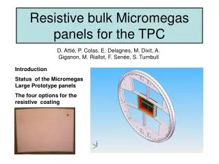
Resistive anode Micromegas • With 2mm x 6mm pads, an ILC-TPC has 1.2 106 channels, with consequences on cost, cooling, material budget… • 2mm still too wide to give the target resolution (100-130 µm) Not enough charge sharing, even for 1mm wide pads in the case of Micromégas (savalanche ~12µm) P. Colas - Micromegas TPC
Solution (M.S.Dixit et.al., NIM A518 (2004) 721.) Share the charge between several neighbouring pads after amplification, using a resistive coating on an insulator. The charge is spread in this continuous network of R, C M.S.Dixit and A. Rankin NIM A566 (2006) 281 SIMULATION MEASUREMENT P. Colas - Micromegas TPC
Al-Si Cermet on mylar Drift Gap MESH Amplification Gap 50 m pillars 25 µm mylar with Cermet (1 MW/□) glued onto the pads with 50 µm thick dry adhesive Cermet selection and gluing technique are essential P. Colas - Micromegas TPC
A point charge being deposited at t=0, r=0, the charge density at (r,t) is a solution of the 2D telegraph equation. Only one parameter, RC (time per unit surface), links spread in space with time. R~1 MW/□ and C~1pF per pad area matches µs signal duration. (r) Q (r,t) integral over pads mm ns P. Colas - Micromegas TPC
Another good property of the resistive foil: it prevents charge build-up, thus prevents sparks. Gains 2 orders of magnitude higher than with standard anodes can be reached. Mesh voltage (V) P. Colas - Micromegas TPC
Reminder of past results • Demonstration with GEM + C-loaded kapton in a X-ray collimated source (M.S.Dixit et.al., Nucl. Instrum. Methods A518 (2004) 721) • Demonstration with Micromegas + C-loaded kapton in a X-ray collimated source (unpublished) • Cosmic-ray test with GEM + C-loaded kapton (K. Boudjemline et.al., to appear in NIM) • Cosmic-ray test with Micromegas + AlSi cermet (A. Bellerive et al., in Proc. of LCWS 2005, Stanford) • Beam test and cosmic-ray test in B=1T at KEK, October 2005 P. Colas - Micromegas TPC
The Carleton chamber Carleton-Saclay Micromegas endplate with resistive anode. 128 pads (126 2mmx6mm in 7 rows plus 2 large trigger pads) Drift length: 15.7 cm ALEPH preamps + 200 MHz digitizers P. Colas - Micromegas TPC
4 GeV/c + beam, B=1T (KEK) Effect of diffusion: should become negligible at high magnetic field for a high t gas P. Colas - Micromegas TPC
The 5T cosmic-ray test at DESY 4 weeks of data taking (thanks to DESY and T. Behnke et al.) Used 2 gas mixtures: Ar+5% isobutane (easy gas, for reference) Ar+3% CF4+2% isobutane (so-called T2K gas, good trade-off for safety, velocity, large wt ) Most data taken at 5 T (highest field) and 0.5 T (low enough field to check the effect of diffusion) Note: same foil used since more than a year. Still works perfectly. Was ~2 weeks at T=55°C in the magnet: no damage P. Colas - Micromegas TPC
The gain is independent of the magnetic field until 5T within 0.5% P. Colas - Micromegas TPC
Pad Response Function P. Colas - Micromegas TPC
Residuals in z slices P. Colas - Micromegas TPC