Download
1 / 60
600 likes | 714 Views
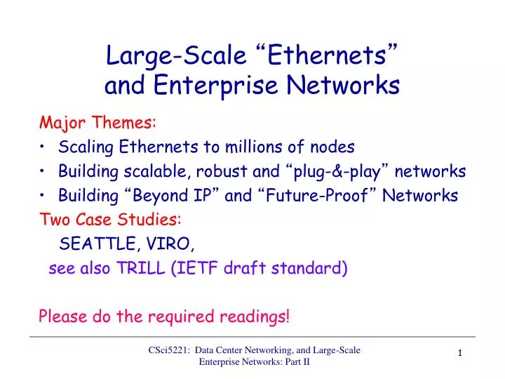
Large-Scale “ Ethernets ” and Enterprise Networks. Major Themes: Scaling Ethernets to millions of nodes Building scalable, robust and “ plug-&-play ” networks Building “ Beyond IP ” and “ Future-Proof ” Networks Two Case Studies: SEATTLE, VIRO,

E N D
Large-Scale “Ethernets”and Enterprise Networks Major Themes: • Scaling Ethernets to millions of nodes • Building scalable, robust and “plug-&-play” networks • Building “Beyond IP” and “Future-Proof” Networks Two Case Studies: SEATTLE, VIRO, see also TRILL (IETF draft standard) Please do the required readings! CSci5221: Data Center Networking, and Large-Scale Enterprise Networks: Part II
Large number of mobile users and systems Large number of smart appliances High bandwidth core and edges But also resource limited elements and networks (e.g., sensors, MANETs) Heterogeneous technologies Current Trends and Future Networks Multimedia Streaming Games Online TV Web/emails Home users Internet (or Future Networking Substrate) Cell & smart phones Surveillance & Security Banking & e-commerce POTS VoIP
Large ISPs and enterprise networks Large data centers with thousands or tens of thousands machines Metro Ethernet More and more devices are “Internet-capable” and plugged in Likely rich and more diverse network topology and connectivity Even within a Single Administrative Domain
Challenges posed by These Trends • Scalability: capability to connect tens of thousands, millions or more users and devices • routing table size, constrained by router memory, lookup speed • Mobility: hosts are more mobile • need to separate location (“addressing”) and identity (“naming”) • Availability & Reliability: must be resilient to failures • need to be “proactive” instead of reactive • need to localize effect of failures • Manageability: ease of deployment, “plug-&-play” • need to minimize manual configuration • self-configure, self-organize, while ensuring security and trust • …….
Quick Overview of Ethernet • Dominant wired LAN technology • Covers the first IP-hop in most enterprises/campuses • First widely used LAN technology • Simpler, cheaper than token LANs, ATM, and IP • Kept up with speed race: 10 Mbps and now to 40 Gbps • Soon 100 Gbps would be widely available Metcalfe’s Ethernet sketch
Ethernet Frame Structure • Addresses: source and destination MAC addresses • Flat, globally unique, and permanent 48-bit value • Adaptor passes frame to network-level protocol • If destination address matches the adaptor • Or the destination address is the broadcast address • Otherwise, adapter discards frame • Type: indicates the higher layer protocol • Usually IP
Interaction w/ the Upper Layer (IP) • Bootstrapping end hosts by automating host configuration (e.g., IP address assignment) • DHCP (Dynamic Host Configuration Protocol) • Broadcast DHCP discovery and request messages • Bootstrapping each conversation by enabling resolution from IP to MAC addr • ARP (Address Resolution Protocol) • Broadcast ARP requests • Both protocols work via Ethernet-layer broadcasting (i.e., shouting!)
Broadcast Domain and IP Subnet • Ethernet broadcast domain • A group of hosts and switches to which the same broadcast or flooded frame is delivered • Note: broadcast domain != collision domain • Broadcast domain == IP subnet • Uses ARP to reach other hosts in the same subnet • Uses default gateway to reach hosts in different subnets • Too large a broadcast domain leads to • Excessive flooding and broadcasting overhead • Insufficient security/performance isolation
Ethernet Bridging: “Routing” at L2 • Routing determines paths to destinations through which traffic is forwarded • Routing takes place at any layer (including L2) where devices are reachable across multiple hops P2P, or CDN routing App Layer Overlay routing IP routing IP Layer Ethernet bridging Link Layer
Ethernet (Layer-2) “Routing” • Self-learning algorithm for dynamically building switch (forwarding) tables • “Eavesdrop” on source MACs of data packets • Associate source MACs with port # (cached, “soft-state”) • Forwarding algorithm • Forwarding algorithm • If dst MAC found in switch table, send to the corresp. port • Otherwise, flood to all ports (except the one it comes from) • Dealing with “loopy” topologies • Running (periodically) spanning tree algorithm to convert it into a tree (rooted at an “arbitrary” node) • 802.11 Wireless LANs use somewhat similar methods • Use the same 48-bit MAC addresses more complex frame structures; • End hosts need to explicitly associate with APs
Pros and Cons of Layer 2 Technologies Pluses: • “Plug-&-Play,” with minimal configuration • But VLAN requires manual configuration! • MAC address: flat-name, host mobility Minuses: • Data plane flooding, not scalable to large networks • Sub-optimal routing (using a single spanning tree) • Can’t deal with complex topology! • Not robust to failures! • if any edge or node on the spanning tree fails, need to re-compute spanning tree; • slow convergence!
Pros and Cons of (Layer 3) IP Pluses: • Better data plane scalability • unicast packets is sent point-to-point! • More “optimal” routing • one spanning tree per destination; • link weights can be used to reflect link bw, latency, load, etc. Minuses: • Two-level hierarchical names & (manual) address management • prefix assignment per link; router configuration • poorer support for mobility; • difficulty/complexity in “re-naming” • Esp., changing addressing schemes (IPv4 -> IPv6 transition) • control plane flooding & reactive approach to failures! • global effect of network failures • Can’t take advantage of rich network topologies (path diversity)!
State of the Practice: A Hybrid Architecture Enterprise networks comprised of Ethernet-based IP subnets interconnected by routers Ethernet Bridging - Flat addressing - Self-learning - Flooding - Forwarding along a tree R R IP Routing (e.g., OSPF) - Hierarchical addressing - Subnet configuration - Host configuration - Forwarding along shortest paths R R Broadcast Domain (LAN or VLAN) R
“All-Ethernet” Enterprise Network? • “All-Ethernet” makes network mgmt easier • Flat addressing and self-learning enablesplug-and-play networking • Permanent and location independent addresses also simplify • Host mobility • Access-control policies • Network troubleshooting
Data Center Networks ! • Data centers • Backend of the Internet • Mid- (most enterprises) to mega-scale (Google, Yahoo, MS, etc.) • E.g., A regional DC of a major on-line service provider consists of 25K servers + 1K switches/routers • To ensure business continuity, and to lower operational cost, DCs must • Adapt to varying workload Breathing • Avoid/Minimize service disruption (when maintenance, or failure) Agility • Maximize aggregate throughput Load balancing
But, Ethernet Bridging Does Not Scale • Flooding-based delivery • Frames to unknown destinations are flooded • Broadcasting for basic service • Bootstrapping relies on broadcasting • Vulnerable to resource exhaustion attacks • Inefficient forwarding paths • Loops are fatal due to broadcast storms; uses the STP • Forwarding along a single tree leads toinefficiency and lower utilization
Layer 2 vs. Layer 3 Again Neither bridging nor routing is satisfactory. Can’t we take only the best of each?
“Floodless” in SEATTLE (Scalable Ethernet ArchiTecTure for Larger Enterprises) • Objectives • Avoiding flooding • Restraining broadcasting • Keeping forwarding tables small • Ensuring path efficiency • SEATTLE architecture • Hash-based location management • Shortest-path forwarding • Responding to network dynamics
Avoiding Flooding • Bridging uses flooding as a routing scheme • Unicast frames to unknown destinations are flooded • Does not scale to a large network • Objective #1: Unicast unicast traffic • Need a control-plane mechanism to discover and disseminate hosts’ location information “Send it everywhere! At least, they’ll learn where the source is.” “Don’t know where destination is.”
Restraining Broadcasting • Liberal use of broadcasting for bootstrapping(DHCP and ARP) • Broadcasting is a vestige of shared-medium Ethernet • Very serious overhead inswitched networks • Objective #2: Support unicast-based bootstrapping • Need a directory service • Sub-objective #2.1: Yet, support general broadcast • Nonetheless, handling broadcast should be more scalable
Keeping Forwarding Tables Small • Flooding and self-learning lead to unnecessarily large forwarding tables • Large tables are not only inefficient, but also dangerous • Objective #3: Install hosts’ location information only when and where it is needed • Need a reactive resolution scheme • Enterprise traffic patterns are better-suited to reactive resolution
Ensuring Optimal Forwarding Paths • Spanning tree avoids broadcast storms.But, forwarding along a single tree isinefficient. • Poor load balancing and longer paths • Multiple spanning trees are insufficient and expensive • Objective #4: Utilize shortest paths • Need a routing protocol • Sub-objective #4.1: Prevent broadcast storms • Need an alternative measure to prevent broadcast storms
Backwards Compatibility • Objective #5: Do not modify end-hosts • From end-hosts’ view, network must work the same way • End hosts should • Use the same protocol stacks and applications • Not be forced to run an additional protocol
SEATTLE in a Slide • Flat addressing of end-hosts • Switches use hosts’ MAC addresses for routing • Ensures zero-configuration and backwards-compatibility (Obj # 5) • Automated host discovery at the edge • Switches detect the arrival/departure of hosts • Obviates flooding and ensures scalability (Obj #1, 5) • Hash-based on-demand resolution • Hash deterministically maps a host to a switch • Switches resolve end-hosts’ location and address via hashing • Ensures scalability (Obj #1, 2, 3) • Shortest-path forwarding between switches • Switches run link-state routing to maintain only switch-level topology (i.e., do not disseminate end-host information) • Ensures data-plane efficiency (Obj #4)
How does it work? Optimized forwarding directly from D to A y Deliver to x x C Host discovery or registration Traffic to x A Tunnel to egress node, A Hash(F(x) = B) Tunnel to relay switch, B Hash (F(x) = B) D Entire enterprise (A large single IP subnet) LS core Notifying<x, A> to D B Store<x, A> atB E Switches End-hosts Control flow Data flow
Terminology shortest-path forwarding Dst Src < x, A > x y A Ingress Egress D < x, A > Ingress appliesa cache eviction policyto this entry Relay (for x) B < x, A >
Responding to Topology Changes h h • The quality of hashing matters! A E h h F Consistent Hash minimizes re-registration overhead B h h h h h D h C
Single Hop Look-up ysends traffic tox y x A E Every switch on a ring is logically one hop away B F(x) D C
< x, G > < x, G > < x, G > Responding to Host Mobility Old Dst Src < x, A > x y when shortest-path forwarding is used A D < x, A > Relay (for x) G B New Dst < x, G > < x, A >
Unicast-based Bootstrapping: ARP • ARP • Ethernet: Broadcast requests • SEATTLE: Hash-based on-demand address resolution 4. BroadcastARP reqfor a b sb Owner of (IPa ,maca) a 5. HashingF(IPa) = ra sa 1. Host discovery 6. UnicastARP reqto ra 2. Hashing F(IPa) = ra 7. Unicast ARP reply(IPa , maca ,sa)to ingress Switch ra End-host 3. Storing (IPa ,maca ,sa) Control msgs ARP msgs
Unicast-based Bootstrapping: DHCP • DHCP • Ethernet: Broadcast requests and replies • SEATTLE: Utilize DHCP relay agent(RFC 2131) • Proxy resolution by ingress switches via unicasting h 4. BroadcastDHCP discovery DHCP server (macd=0xDHCP) 6. DHCP msg to r 8. Deliver DHCP msg to d sh d 5. HashingF(0xDHCP) = r sd 1. Host discovery 7. DHCP msg to sd 2. Hashing F(macd) = r Switch r End-host 3. Storing (macd ,sd) Control msgs DHCP msgs
Control-Plane Scalability When Using Relays • Minimal overhead for disseminating host-location information • Each host’s location is advertised to only two switches • Small forwarding tables • The number of host information entries over all switches leads to O(H), not O(SH) • Simple and robust mobility support • When a host moves, updating only its relay suffices • No forwarding loop created since update is atomic
Data-Plane Efficiency w/o Compromise • Price for path optimization • Additional control messages for on-demand resolution • Larger forwarding tables • Control overhead for updating stale info of mobile hosts • The gain is much bigger than the cost • Because most hosts maintain a small, static communities of interest (COIs) [Aiello et al., PAM’05] • Classical analogy: COI ↔ Working Set (WS);Caching is effective when a WS is small and static
SEATTLE: Summary • SEATTLE is a plug-and-playable enterprise architecture ensuring both scalability and efficiency • Enabling design choices • Hash-based location management • Reactive location resolution and caching • Shortest-path forwarding • Lessons • Trading a little data-plane efficiency for huge control-plane scalability makes a qualitatively different system • Traffic patterns are our friends
VIRO: Virtual Id Routing • Goal • How are the nodes (racks) inter-connected? • Typically a hierarchical inter-connection structure • Today’s typical data center structure Cisco recommended data center structure: starting from the bottom level • rack switches • 1-2 layers of (layer-2) aggregation switches • access routers • core routers • Is such an architecture good enough?
VIRO: Virtual Id Routing A Scalable, Robust, “Plug-&-Play” and Namespace-Independent Routing Arch. for “Future” Networks (beyond simply large-scale Ethernets, …) • Key Features • Separate identities (identifiers) from locations (locators) • introduce (“hierarchical”) virtual ids as “locators” • a “topology-ware”, self-organizing vid layer • Decouple routing/forwarding from addressing/naming • unify (traditional) layer 2 & layer 3 data plane operations • routing/forwarding done using vid’s only (except first/last hop) • Support any namespaces (identifiers), whether flat or not! • “native” or “application” naming/address-independent • co-existence and inter-operability between diff. namespaces! • “future-proof”
VIRO: Virtual Id Routing … • More Key Features … • Highly scalable, and fully take advantage of path diversity • DHT-like routing paradigm --- beyond shortest-path routing! • O(log N) routing table size • Ease to support multi-path routing & dynamic load-balancing • And highly robust • eliminate (network-wide) control plane flooding! • localize failures, enable fast rerouting (pro-active!) • Other Important features • Allow for (logically centralized) network management • access and other policy control • also facilitate other security mechanisms • Can easily be adapted to support multiple topologies or virtualized network services
C D D G G C E A B A E B F F Virtual Id Layer and Vid Space • Topology-aware, structured virtual id (vid) space • Kademlia-like “virtual” binary tree • self-configurable and self-organizing E B A C F Other App Namespaces IPv4/IPv6 Virtual ID Layer G D Layer 2 Physical Network Topology
VIRO: Three Core Components • Virtual id space construction and vid assignment • performed most at the bootstrap process (i.e., network set up): • a vid space “skeleton” is created • once network is set up/vid space is constructed: • a new node (a “VIRO switch”) joins: assigned based on neighbors’ vid’s • end-host/device: inherits a vid (prefix) from “host switch” (to which it is attached), plus a randomly assigned host id; host may be agnostic of its vid • VIRO routing algorithm/protocol: • DHT-style, but needs to build end-to-end connectivity/routes • a bottom-up, round-by-round process, no network-wide control flooding • O(log N) routing entries per node, N: # of VIRO switches • (Persistent) layer-2/3 address/name resolution and vid look-up • DHT directory services built on top of the same vid space • “persistent” identifier (e.g., MAC/IP address) hashed to a “vid” key, which is then used for (pid, vid) mapping registration, look-up, etc. • Data forwarding among VIRO switches using vid only
Vid Assignment: Bootstrap Process 1 0 0 1 0 1 0 1 1 0 1 0 0 1 D G F A E B • Initial vid assignment and vid space construction performed during the network bootstrap process • Depending on network operating environments, can be performed using either a centralized or distributed vid assignment algorithm, e.g., • top-down graph-partition (centralized) • bottom-up clustering (distributed) C
Vid Assignment: Key Properties 1 0 0 1 0 1 L 0 1 1 0 1 0 0 1 D G F A E B • Logical distance defined on the vid space d(vidx, vidx):= L – lcp (vidy,vidy) -- L: max. tree height; lcp: longest common prefix • Key invariant properties (to ensure “topology-aware”): • closeness: if two nodes are close in the vid space, then they are also close in the physical topology • esp., any two logical neighbors must be directly connected. • connectivity:any two adjacent logical sub-trees must be physically connected. C
VIRO Routing: Key Features • Inspired by Kademlia DHT • but need to build end-to-end connectivity/routes! • Bottom-up, round-by-round process • first: neighbor discovery • then: build routing entries to reach nodes within each level of the vid space (virtual binary tree) • use “publish-query” mechanisms • Highly scalable: O(L) routing entries per node • L ~ O(log N), N: number of nodes (VIRO switches) • more importantly, path diversity (e.g., multi-path routing) can be naturally exploited for load-balancing, etc. • routing is no longer “shortest” path based ! • No single point of failure, and localize effect of failures • unlike link state routing, node/link failure/recovery is notflooded network-wide; impact scope is limited • also enable localized fast rerouting • Completely eliminate “network-wide” control flooding
VIRO Routing: Some Definitions • For k =1, …, L, and any node x: • (level-k) sub-tree, denoted by Sk(x): • set of nodes within a logical distance of k from x • (level-k) bucket, denoted by Bk(x): • set of nodes exactly k logical distance from node x • (level-k) gateway, denoted Gk(x): • a node in Sk-1(x) which is connected to a node in Bk(x) is a gateway to reach Bk(x) for node x; a direct neighbor of x that can reach this gateway node is a next-hop for this node Example: S1(A)= {A,F}, B1(A)={F}, G1(A)={A} S2(A) ={A,C,F}, B2(A)={C} G2(A)={A}, S3(A) = {A,B,C,D,E,F,G} B3(A) = {B,D,E,G} G3(A) = {C,F} S3(A) S2(A) B3(A) S1(A) B2(A) 1 0 0 1 0 1 0 1 1 0 1 0 0 B1(A) 1 D G F A E B C
VIRO Routing: Some Specifics • Correctness of the algorithm can be formally established. Bottom-up, “round-by-round” process: • round 1: neighbor discovery • discover and find directly/locally connected neighbors • round k ( 2 <= k <= L): • build routing entry to reach level-k bucket Bk(x) -- a list of one or more (gateway, next-hops) • use “publish-query” (rendezvous) mechanisms Algorithm for building Bk(x) routing entry at node x: • if a node(x) is directly connected to a node in Bk(x), then it is a gateway for Bk(x), and also publishes it within Sk-1(x). • nexthop to reach Bk(x) = direct physical neighbor in Bk(x) • else node x queries within Sk-1(x) to discover gateway(s) to reach Bk(x) • nexthop to reach Bk(x) = nexthop(gateway)
M C N H D G A L J E B F K VIRO Routing: Routing TableAn Example - - - - - - - - - - - - - - - - - - - 01000 00100 01001 10110 00000 00110 11000 10100 10000 11110 00010 10010 11100 1 From node A’s perspective: Buckets from level 1 to L(=5) 0 1 1 0 0 0 1 1 1 0 1 0 0 1 0 0 1 1 1 0 1 0 1 1 1 1 1 1 0 1 0 1 0 1 0 0 1 0 0 0 0 0 1 1 E F G H J K L A B C D M N
M C N H D G A L J E B F K VIRO Routing: Example • E.g. Node A: discover three direct neighbors, B,C,D; • build the level-1 routing entry to reach B1(A)={} 01000 00100 01001 10110 00000 00110 11000 10100 10000 11110 00010 10010 11100 Routing Table for node A • Round 1: • each node x discovers and learns about its directly/locally connected neighbors • build the level-1 routing entry to reach nodes in B1(x)
M C N H D G A L J E B F K VIRO Routing: Example … • E.g. Node A: B2(A)={B}; • node A directly connected to node B; • publish itself as gateway to B2(A) 01000 00100 01001 10110 00000 00110 11000 10100 10000 11110 00010 10010 11100 Routing Table for node A • Round 2: • if directly connected to a node in B2(x), enter self as gateway in level-2 routing entry, and publish in S1(x) • otherwise, query “rendezvous point” in S1(x) and build the level-2 routing entry to reach nodes in B2(x)
M C N H D G A L J E B F K VIRO Routing: Example … 01000 00100 01001 • E.g. Node A: B3(A)={C,D}; • A publishes edges A->C, A->D to “rendezvous point” in S2(A), say, B; 10110 00000 00110 11000 10100 10000 11110 00010 10010 11100 • Round 3: • if directly connected to a node in B3(x), enter self as gateway in level-3 routing entry, and publish in S2(x) • otherwise, query “rendezvous point” in S2(x) and build the level-2 routing entry to reach nodes in B3(x)
M C N H D G A L J E B F K VIRO Routing: Example … 01000 • E.g. Node A: B4(A)={M,N}; • A queries “rendezvous point” in S3(A), say, C; learns C as gateway 00100 01001 10110 00000 00110 11000 10100 10000 11110 00010 10010 11100 • Round 4: • if directly connected to a node in B4(x), enter self as gateway in level-4 routing entry, and publish in S3(x) • otherwise, query “rendezvous point” in S3(x) and build the level-4 routing entry to reach nodes in B4(x)
VIRO Routing: Example … • E.g. Node A: B5(A)={E,F,G,H,J,K,L}; • A queries “rendezvous point” in S4(A), say, D; learns B as gateway 01000 00100 M C 01001 N H 10110 00000 D G A 00110 11000 10100 L 10000 J 11110 E B F K 00010 10010 11100 • Round 5: • if directly connected to a node in B5(x), enter self as gateway in level-5 routing entry, and publish in S4(x) • otherwise, query “rendezvous point” in S4(x) and build the level-4 routing entry to reach nodes in B5(x)