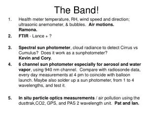
Download
1 / 29

E N D
The BAND-GEM detector G. Croci1,2,3, A. Muraro1, G. Grosso1, E. Perelli Cippo1, G. Albani3, C. Cazzaniga3, G. Claps4,, F. Murtas4, M. Rebai2,4, M. Tardocchi1, C. Höglund5,6, L. Hultman6, J. Birch6, R. Hall-Wilton6,7, Xiao-Xiao Cai5,8, I. Llamas Jansa5,8 and G. Gorini3,4 1Istituto di Fisica del Plasma (IFP-CNR) – Via Cozzi 53, 20125 Milano, Italy 2INFN – Sez. Di Milano-Bicocca – Piazza della Scienza 3, 20126 Milano, Italy 3Dipartimento di Fisica, Università degli Studi di Milano-Bicocca – Piazza della Scienza 3, 20126 Milano, Italy 4INFN – Laboratori Nazionali di Frascati –Via Fermi 40, 0044 Frascati, Italy 5European Spallation Source ESS AB, P.O. Box 176, SE-221 00 Lund, Sweden 6Department of Physics, Chemistry and Biology (IFM), Thin Film Physics Division, Linköping University, SE-581 83 Linköping, Sweden 7Mid-Sweden University, SE-851 70 Sundsvall, Sweden 8IFE: Institute for Energy Technology, Box 40, 2027 Kjeller, Norway G. Croci on behalf of GEM Financial support from CNR; ESS pre-construction in-kind contract
SHOULD WE DETECT THERMAL NEUTRONS WITH GEMS? • GEM detectors born for tracking and triggering applications (detection of charged particles).... • ...but if coupled to a solid state converter they can detect • Thermal Neutrons 10Boron converter • Neutrons are detected using the productus (alpha,Li) from nuclear reaction 10B(n,alpha)7Li • Face 3He world shortage • GEMs offer the following advantages • High rate capability(up to MHz/mm2) suitable for high flux neutron beams like at ESS • Submillimetric space resolution (suited to experiment requirements) • Time resolution from 5 ns (gas mixture dependent) • Possibility to be realized in large areas and in different shapes • Radiation hardness • Low sensitivity to gamma rays (with appropriate gain) G. Croci et Al JINST 7 C03010; F. Murtas et Al, JINST 7 P07021; G. Croci et Al,NIMA 720, 144; G. Crociet Al, NIMA, 712, 108; G. Croci et Al, JINST 8 P04006; G. Croci et Al, NIMA 732, 217; G. Albani et Al, JINST 10 C04040; G. Crociet Al, EPJP 130, 118G. Croci et Al, EPL, 107 12001 G. Crociet Al, Prog. Theor. Exp. Phys. 083H01;
OUTLINE • THE BANDGEM DETECTOR • Principle of operation • Detector Simulation • Results • APPLICATION @ LOKI-ESS • LOKI Demonstrator
Boron Array Neutron DetectorBANDGEM Thermal neutron detector
Scheme and Principle of operation n θ n Al2O3 10 cm Cathode α 3D Lamella System 6 cm α 10B4C 10B4C Ed e- 2 mm 10B4C 10B4C Triple GEM Al2O3 Padded Anode Alumina Lamellas coated on both sides with 10B4C Using low θ values (few degs) the path of the neutron inside the B4C is increased Higher efficiency when detector is inclined
The lamellas Material = Allumina (Al2O3) 6 cm A lamella is composed by 15 strips 12 cm 2 mm 2 mm
10B4C Coating on the lamellas Deposition done by Dr. Carina Hoglund The resulting coated lamellas A 1 μm 10B4C coating has been deposited on both sides of the lamella and on all the 15 strips In total more than 50 lamellas have been coated 50 Lamellas are necessary to assembly the first detector prototype Coatings are slightly conductive ρ = 696 Ω*cm
Detector Assembly The full Lamella System. A total of 48 lamellas have been mounted mounted. Their distance is 2 mm 128 Pads of area 6x12 mm2 have been used as anode Assembly with Triple GEM detector
BANDGEM simulation Numerical Simulation of Neutron conversion efficiency and electron extraction 2mm B4C=2mm GAS=2mm Volumetric Simulation (1000 e-) Diffusion ON Good Electron 1000, Out Electron 263 Percentage 26.3 Volumetric Simulation (1000 e-) Diffusion OFF Good Electron 1000, Out Electron 486 Percentage 48.6
Detector test at IFE (JEEP II Reactor, RD2D beamline) Ed = 230 V/cm Et1=Et2= 3 kV/cm; Ei = 5 kV/cm Mixture Ar/CO2 70%/30% 230 cc/min Carioca chips FPGA-LNF Motherboard Angle = 7 degrees VGEM = 980 V
High Voltage Scan – Working point Ed = 230 V/cm Et1=Et2= 3 kV/cm; Ei = 5 kV/cm Mixture Ar/CO2 70%/30% 230 cc/min Need to understand the gamma ray background component. On-site measurment with a gamma source VGEM working point values are higher than usual one (870 V) Neutron energy En = 34.5 meV
Angular scan Neutron energy En = 34.5 meV Beam size = 9 mm x 9 mm The counting rate depends on the angle between the beam and the lamellas. There is about 0.5of systematic error settings due to the mechanics The 3He tube in front of the GEM is counting 14660 n/s with an efficiency of 87% at this neutron energy. It is fully in the beam
Comparison 3He -GEM 3He tube has a diameter of 2.54 cm We see the same behaviuor (inverted in 3He for the same angles). The GEM is absorbing neutrons. There are still some feautures to be understood Maxima and minima are due to the geometry of the GEM En = 34.5 meV n 3He Slits GEM GEM is used as absorber
First efficiency estimation as a function of wavelenght ε(λ) = 1 – e-cσ(λ) Where σ(λ) = λ/ λ0 If λ=λ0=1.54 A ε=0.15 for 10 degrees and ε==0.20 for 7 degrees (Angle with respect neutron direction)
BANDGEM detector for neutron diffraction measurements INES (ISIS) sample pos. Same Measurement Time • First BANDGEM Prototype • Bronze sample • BANDGEM @ 90° • 3He counts about 3.4 times the BANDGEM • BANDGEM/3He Solid Angle Ratio = 0.45 Transmitted neutron beam BANDGEM Incident neutron beam 3He Tube GEM position
BANDGEM application @ LOKI ....Just an example of a possible LOKI vessel Configuration... BANDGEM Modules As rear detector panels • Requirements for rear detector panel • Rate Capability = 40 kHz/cm2 • Time resolution bettter than 1 ms • Efficiency of about 60% at 4 Å • X-Y Space resolution of about 4 mm Construction of BANDGEM demonstrator for LOKI as an upgrade of the first prototype
The BANDGEM umbrella for LOKI 337 mm 400 mm Readout anode 2 GEM 3 2 GEM 2 2 GEM 1 6 Lamellae system Total active area: 647 cm2 96 8 Cathode
Detector Assembly – The cake Readoutanode Triple GEM Lamellassystem Aluminatemylarcathode
Digital Chip with 8 channels Equips the LHCb GEM detectors Fast chip – used for triggering Adapted from MWPC The Front End Electronics The first protoype electronics is based on Carioca Chip. Total dimension : 3x6 cm2 A new chip is being tested: the GEMINI chip. Mixed analog and digital chip that Has 16 channels/chip. This is the chip that we would like to use at ESS for LOKI BANDGEM Especially developed for GEM detectors
Conclusions • First BANDGEM prototype reached an efficiency of 20% at 1.54 Å • First BANDGEM prototype successfully tested as neutron diffractometer improvement w.r.t. single layer • BAND-GEM demonstrator for LOKI • New simulation • Higher efficiency • Being designed • Small area prototype ready before end 2015 • Geant4 simulations on-going.
Complete GEM detector system Charged particles X Ray Gammas Neutrons 12 V PS HVGEM LNF HV Filters 3 GEM detector with padded anode (Carioca Chips) FPGA Board LNF 128 ch DAQ PC Current Monitor 2D monitor with pads readout Possibility to set time slices from 5 ns up to 1 s
Resistivity measurements of the B4C coatings Measurement performed (using the 4 points method) on the first (preliminary) alumina sample coated by Carina with 1 μm of B4C Since the thickness of the sample was 1 μm the measured resistivity ρ = 696 Ω*cm The coatings can be considered as partially conductive In collaboration with CNR-IMIP
Detector Assembly (3) 128 Pads of area 6x12 mm2 have been used as anode Assembly with Triple GEM detector 12 mm 2 mm Lamella disposition on the pads 6 mm
GEM Foil The GEM foils will be realized at CERN and they will be glued to their frames using the same technique used for the production of the cathode. Each GEM foil will be sectorized in 8 sectors, in order to reduce the possible damage caused by a spark. A total of 3 GEM (triple GEM) will be installed in the detector and the gap between each GEM (Transfer gaps) is equal to 2mm. All the GEM foils will be sandwiched and glued on the upper trapezoidal frame.
Padded Anode The anode will be composed by 1024 pads. The the size of the pads is between 7.7 and 137 mm2. The maximum pad size is similar to the one of the nGEM for SPIDER, and we have already tested the low noise level. The PADs is divided into 10 ϕsectors, whilethe dimension of the PADs is constant along the y-coordinate and equal to 4mm. At the moment only the PADs were designed, while the position of the read-out electronics is still under investigation. The design of the read-out electronic position will be decided after the test of the GEMINI Chip. The anode will be glued on the GEM3 frame, and the gap between the GEM3 and the PADs (induction gap) will be equal to 2mm. y ϕ
Small Area Prototype- for testing In order to test the technology processes that will be used for the construction of the demonstrator and to validate the numerical simulation as soon as possible, it was decide to made a small scale prototype (active area=10x10 cm2). 107 mm With this detector we can test the production method of the lamellae system (it is the same of the demonstrator) and we can validate the numerical simulations. It will be composed by 25 lamellae (all with the same dimensions) and the 10x10 triple GEM system with its cathode will be the same of the actual BandGEM (and of the other 10x10 GEM detectors such as the bGEM) . This should allow the production and the test of the detector up to the end of this year. 115 mm