Download
1 / 32
320 likes | 451 Views
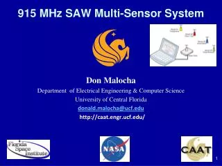
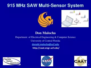
915 MHz SAW Multi-Sensor System. Don Malocha Department of Electrical Engineering & Computer Science University of Central Florida donald.malocha@ucf.edu http://caat.engr.ucf.edu/. Timeline of OFC Wireless Results. UCF Wireless Demonstrations:

E N D
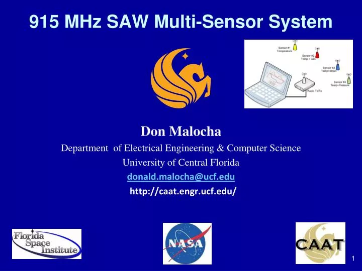
915 MHz SAW Multi-Sensor System Don Malocha Department of Electrical Engineering & Computer Science University of Central Florida donald.malocha@ucf.edu http://caat.engr.ucf.edu/
Timeline of OFC Wireless Results • UCF Wireless Demonstrations: • Sensors: temperature, range, strain, hydrogen, magnetic, liquid, and cryogenic. • Environments: isotropic, hallways (60m), faraday cage (.5x.5 m), anechoic
Confluence of Technology • SAW design, analysis and simulation • RF receiver technology – fast & cheaper • Post-processing – fast & cheaper • Hardware – design, cost, performance, etc. • SAW sensor embodiments • On-board sensors • Off-board sensors
Schematic of OFC SAW ID Tag Sensor bandwidth is dependent on number of chips and sum of chip bandwidths. Frequency domain of Bragg reflectors: contiguous in frequency but shuffled in time Time domain chips realized in Bragg reflectors having differing carrier frequencies and frequencies are non-sequential which provides coding
UCF Fast Prototyping Mask (0.8 um resolution) to System <1 week from idea to prototype
Complex SAW Coupling-of- Modes Analysis, Modeling, Synthesis & Data Extraction
Example 915 MHz SAW OFC Sensor f4 f3 f1 f5 f2 Photo Micrograph US Quarter SAW Sensor SAW OFC Reflector Chip Code FFT Acoustic Delay Noise-like spectrum
Confluence of Technology • SAW design, analysis and simulation • RF receiver technology – fast & cheaper • Post-processing – fast & cheaper • Hardware – design, cost, performance, etc. • SAW sensor embodiments • On-board sensors • Off-board sensors
RF Component Advances • RF components cost a few cents and ADC’s are rapidly lowering cost for broad bandwidth signal processing • Texas Instruments, Linear Technology, RFMD, Triquint, Maxim and many others, offer RF components, transceivers and ADC on a chip • Transceiver systems can now be custom built in the 433 to 2400 MHz bands at reasonable development and production costs • Huge number of applications • ASIC development as volumes increase
Confluence of Technology • SAW design, analysis and simulation • RF receiver technology – fast & cheaper • Post-processing – fast & cheaper • Hardware – design, cost, performance, etc. • SAW sensor embodiments • On-board sensors • Off-board sensors
UCF Synchronous Transceiver- Software Radio (2004-2010) • Pulse Interrogation: Chirp or RF burst • Correlator Synchronous Receiver • Integration of multiple “pings” • OFC processing gain • Software Radio Based • Reconfigurable • application specific
Target Gain vs. FrequencyAnalysis points to ~1 GHz wherefis in GHz Good fo region %BW SAW, antenna and net gain in dB, and fractional bandwidth, versus frequency for a 3cm radius ESA. Assumes a SAW propagation length of 5 usec.
Background • There have been previous sensor and RFID analysis approaches, most notably by Buff, Siefert, Pohl, Reindl, Kuypers, Kalinin, Hartmann, Plessky, and many others • We desired a universal time delay extraction approach, independent of signal waveform • Fast, accurate, and re-configurable • Applicable to multi-pulse sensors
COHERENT CORRELATOR DISCUSSION It’s all about S/N Ratio • Transceiver: time duplexed mode, opposing on-off state. • Transceiver: synchronous mode for switching and integration. • Interrogation signal: wideband, time-pulse (optimized for device code) • Transceiver output: windowed time domain (or frequency domain sweep) to a post-processor.
Example: Hardware Synchronous TDM Pulsed Transceiver A heterodyne coherent correlator transceiver block diagram for use in a multi-sensor SAW system with 3 SAW sensors within the antenna range. The system assumes a wide-band pulsed transmit signal, and time duplexed between transmit and receive cycles. The output from the ADC is input to a post processor that is typically a software based signal-processor.
System Demonstration • OFC SAW sensors developed by UCF • 5 chip OFC delay line sensor • 0.8 um electrodes • Correlator software developed by UCF for demonstrations • 915 MHz synchronous transceiver developed by Mnemonics, Inc. and delivered on NASA STTR contract
Confluence of Technology • SAW design, analysis and simulation • RF receiver technology – fast & cheaper • Post-processing – fast & cheaper • Hardware – design, cost, performance, etc. • SAW sensor embodiments • On-board sensors • Off-board sensors
Example of Problem: Dual-Track OFC Gas Sensor • Dual track device: track#1 as reference and track#2 for thin film sensor • Coded dispersive pulses Actual device with RF probe Differential Mode OFC Sensor Schematic Ultra-thin, nano-clusters Film thickness: 10-50 Ang.
Matched Filter Properties • A symmetric time domain pulse compression, regardless of the nature of the signal. • Compressed peak time pulse is well defined and detectable. • Non-dispersive, linear phase, band-limited frequency response. • MF is purely real in both domains • Quadrature noise may be eliminated, increasing the effective S/N by 3 dB.
Correlator Time Delay Extraction (CTDE) Approach • Received signal: HR(f) = sum of all sensors in range + noise + other • MF each received sensor coded signal • Process magnitude • Process phase • Eliminate imaginary term for coherent integration by removing signal delay • Maximize S/N ratio in delay extraction
Adaptive Temperature Correlator Comparison of ideal and measured matched filter of two different SAW sensors : 5-chip frequency(below) Normalized amplitude (dB) versus time NS401 NS403 Stationary plots represent idealized received SAW sensor RFID signal at ADC. Adaptive filter matches sensor RFID temperature at the point when maximum correlation occurs.
Device Measurements • MNI Transceiver • 915 MHz, Δf=72 MHz • 5-chip OFC • 700 nsec chirp, Ppp_out=28dBm, E=1μJ • 12-bit ADC • NF~14 dB • 2 dBi folded dipole • Nsum=4 • 5 μsec time window • ΔT=±150C, dT=±2C Sensor Range: Random from 1-4 meter radius OFC 8-sensor detection system results in an open-atrium from approximately 4 meters in range. Synchronous integration of 4 sweeps per sample.
Current System Isotropic propagation prediction of S/N versus range for synchronous interrogations (NSUM) = 4, 10, and 100, for a 915 MHz Mnemonics- transceiver using a 5-chip OFC SAW sensor. The S/N determines the precision and accuracy of the extracted sensor information. Current range A 12-bit ADC, Po=28dBm, TxRxantenna=2 dBi, NF= 14 dB, and SAW sensor loss = 10dB
FUTURE FOR SAW SENSOR SYSTEMS Projected range A 16-bit ADC, Po=30dBm, TxRxantenna=20 dBi, NF= 6 dB, and SAW sensor loss = 4dB Isotropic propagation prediction of S/N versus range for synchronous interrogations (NSUM) = 4, 10, and 100, for a 915 MHz transceiver using a 5-chip OFC SAW sensor. The S/N determines the precision and accuracy of the extracted sensor information.
Confluence of Technology • SAW design, analysis and simulation • RF receiver technology – fast & cheaper • Post-processing – fast & cheaper • Hardware – design, cost, performance, etc. • SAW sensor embodiments • On-board sensors • Off-board sensors
Wireless OFC Gas On-Board Sensor • MOVIE
Wireless OFC Demonstration • MOVIE
#1 On-Board Integrated Closure Sensor #2 External sensor; the OFC SAW is the RFID and sensor used to modulate Magnetic puck
#2: 915MHz OFC-SAW-tag and antenna closure sensor • SAW is used as RFID link and external device provides sensing • Sensor between antenna and SAW • on-off ratio • >30dB • Multi-track
Thank You! Acknowledgments • The author gratefully acknowledges the continued support from NASA Kennedy Space Center, and Dr. Robert Youngquist for his encouragement and technical discussions. • This work was partially supported by grants from the Florida High Tech Corridor Council and the Florida Space Institute. • MNI for transceiver development