Download

1 / 140
1.4k likes | 1.56k Views
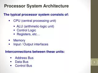
PROCESSOR ARCHITECTURE. Jehan-François Pâris jparis@uh.edu. Chapter Organization. Logic design conventions Implementation of a "toy" CPU Pipelining Pipelining hazards Data hazards Control hazards Exceptions Parallelism. IMPORTANT. LOGIC DESIGN CONVENTIONS.

E N D
PROCESSOR ARCHITECTURE Jehan-François Pâris jparis@uh.edu
Chapter Organization • Logic design conventions • Implementation of a "toy" CPU • Pipelining • Pipelining hazards • Data hazards • Control hazards • Exceptions • Parallelism IMPORTANT
Combinational/state elements • Combinational elements: • Outputs only depend on current inputs • Stateless • Adders and, more generally, arithmetic logic unit (ALU)
Combinational/state elements • State elements: • Have a memory holding a state • Output depends on current inputs and state of element • State reflects past inputs • Flip-flops, …
Judicial analogy • In our legal system • Guilty/not guilty decision is stateless • Good reasons • Sentencing decision is not • "Three strikes and you are out" laws • Good reasons
Clocking methodology • We will assume an edge-triggered clocking technology • Edge is short-enough to prevent data propagation in state elements • Can read current state of a memory element at the same time we update it
Clocking convention • Omit write control signal if state element is updated at every active clock edge
Motivation • "Toy" CPU will implement a subset of MIPS instruction set • Subset will be • Self-sufficient • Simpler to implement • Complex enough to allow a serious discussion of CPU architecture
The subset • Will include • Load and store instructions:lw (load word) and sw (store word) • Arithmetic-logic instructions:add, sub, and, or and slt (set less than) • Branch instructions:beq (branch if equal) and j (jump)
Load and store instructions • Format I • Three operands: • Two registers $r1 and $r2 • One displacement d • lw $r1, d($r2) loads into register $r1 main memory word at address contents($r2) + d • sw $r1, d($r2) stores contents of register $r1 into main memory word at address contents($r2) + d
Arithmetic-logic instructions • Format R • Three operands: • Three registers $r1, $r2 and $r3 • Store into register $r1 result of $r2 <op> $r3where <op> can be add, subtract, and, oras well as set if less than
Branch instruction • Format I • Three operands: • Two registers $r1 and $r2 • One displacement d • beq $r1, $r2, dset value of PC to PC+4 + 4×diff $r1 = $r2
The simplest data path • Assume CPU will do nothing but • Incrementing its program counter and • Deliver the next instruction
The simplest data path Add 4 InstructionMemory Read address Instruction PC
Implementing R2R instructions • Takes two 32-bit inputs • Returns • A 32-bit output • A 1-bit signal if the result is zero
The register file • Two read outputs that are always available • One write input activated by a RegWrite signal • Three register selectors
5 5 The register file Read select 1 Read data 1 Read select 2 Read data 2 Write select Write data 5 RegWrite:enables register writes
Implementing R2R instructions Registerfile ALU Result RegWrite is enabled
Implementing load and store • Require • An address calculation: • contents($r2) + d • An access to data memory • Before doing the address calculation, we must transform 16-bit displacement d into a 32-bit value using sign extension
The data memory • One address selector • One write data input • One read data output • Two controls • MemWrite • MemRead
0000 0000 0000 0000 0110 1010 1010 0100 Sign extension (I) • If 16-bit number has a zero as MSB • It is positive • Must add 16 zero bits 0110 1010 1010 0100
1111 1111 1111 1111 1110 1010 1010 0100 Sign extension (II) • If 16-bit number has a one as MSB • It is negative • Must add 16 one bits 1110 1010 1010 0100
The data memory MemWrite: enables memory writes Memory address Read data Write data MemRead: enables memory reads
Implementing the store instruction Registerfile ALU Address Read Write SE Sign-extended d field
Implementing the load instruction Registerfile ALU Address Read Write SEd field SE
Implementing conditional branch • Target Address: • Sign-extend 16-bit immediate part of instruction • Shift left 2 • Add to PC • Branch Control Logic: • Perform test operation on two registers • Check result
SE Implementing conditional branch Branch Destination PC+4 Add Shiftleft 2 Registerfile To branch control logic ALU d field of instruction Sign-extended d field
Note • Arithmetic-logic operations only use • Register file and ALU • Load and store use • ALU for computing memory address • Data memory
Left to be done • All control signals: • Two multiplexers: ALUSrc and MemtoReg • RegWrite, MemRad and MemWrite switches • ALU controls (4 bits)
Controlling the ALU • Recall that all R-format instructions have same opcode • Operation performed by ALU is specified in the function field (bits <0:5>)
Controlling the ALU • ALU control inputs generated by two-step process • Construct two ALUOp control bits fromopcode • Construct four ALU control bits using • Two ALUop bits • Six bits from function fieldwhen they are needed
Notes • Two step process simplifies combinatorial logic • Many don't care conditions in truth table
Note • Bits 4 and 5 of function field are not used • ALUOp bits only have three possible values:00, 01 and 10 • Introduces don't care conditions • All R instructions use same data paths • Other control bits depend only on opcode
Note • PCSrc is asserted when • Instruction is a branch and • ALU Zero result bit is asserted • We will introduce a Branch control line
The “weird" jump instruction • Uses J format • Single 26 bit operand • Implements an unconditional jump • New value of PC is obtained as follows • Bits 1:0 are zero (address is multiple of 4) • Bits 28:2 come from jump operand • Bits 31:29 come from PC+4