Download
1 / 30
300 likes | 464 Views
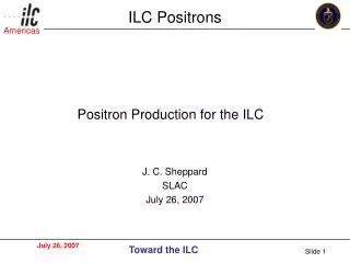
ILC electron cloud R&D program: SLAC. Motivation ILC Positron Damping Ring 6.6km will suffer Electron Cloud in magnets R&D Goals: Reduce surface Secondary Electron Yield (SEY) below electron cloud threshold for ILC DR: SEY ≤ 1.2 Surface approaches Thin film coatings TiN or NEG

E N D
ILC electron cloud R&D program: SLAC • Motivation • ILC Positron Damping Ring 6.6km will suffer Electron Cloud in magnets • R&D Goals: • Reduce surface Secondary Electron Yield (SEY) below electron cloud threshold for ILC DR: SEY ≤ 1.2 • Surface approaches • Thin film coatings TiN or NEG • Electron and photon conditioning in beam line • Clearing electrodes • Grooved surfaces • Projects: • ONGOING: conditioning TiN and NEG coatings in PEP-II straights • ONGOING: rectangular groove chambers in PEP-II straights • PLAN: TiN coated chambers in PEP-II new magnets, FY07-FY08 • PLAN: clearing electrode and groove chambers in magnets KEKB, FY08 M. Pivi, SLAC Jul 26, 2007
SEY GROOVE 1 FLAT 1 GROOVE 2 FLAT 2 ENERGY ANALYZER COLLECTORS THERMOCOUPLES SLAC test chambers installation SEY TEST STATION GROOVE CHAMBERS EXPERIMENT SEY station can be used to expose samples to PEP-II beam environment and then measure the Secondary Electron Yield in lab setup (transport in Ultra-High Vacuum load-lock) Grooved and Flat chambers installed to measure performance inPEP-II beam environment
SEY test station: TiN and NEG Expose samples to PEP-II LER synchrotron radiation and electron conditioning. Then, measure Secondary Electron Yield (SEY) in laboratory. Samples transferred under vacuum. RF seal location PEP-II LER side 20mm Exposed to beam line Complementary at SPS and KEK studies
SEY test station in PEP-II LER (SLAC) PEP-II LER e+ 2 Sample locations inside beam line Manipulator at 0o Isolation valves Manipulator at 45o ILC tests, M. Pivi et al. – SLAC
Transferring system connected to lab set-up (SLAC) SEY analysis chamber Connected for UHV sample transferring Transferring system with sample (UHV) ILC tests, R. Kirby et al. SLAC Manipulator valve Isolation valve
Results of Conditioning in PEP-II LER beam line Before installation in beam line After conditioning e- dose > 40mC/mm**2 ILC tests, M. Pivi et al. – SLAC SEY of Tin-samples measured before and after 2-months conditioning in the beam line. 2 samples inserted respectively in the synchrotron radiation fan plane (0o position) and out of this plane (45o). Similar low SEY recently measured in situ in KEKB beam line S. Kato, Y. Suetsugu et al.
Surface analysis: Carbon content decrease X-ray Photon Spectroscopy. XPS Before installation XPS After exposure in PEP-II LER for 2 months (e dose 40mC/mm^2) LER#1 ILC tests, M. Pivi et al. – SLAC Carbon content is strongly reduced after exposition to PEP-II LER synchrotron radiation + electron + ion conditioning. This is a different result if compared to electron (only) conditioning in laboratory set-up where carbon crystals growth has been observed by many laboratories.
Surface analysis: Carbon content decrease X-ray Photon Spectroscopy. Carbon content is strongly reduced after exposition to PEP-II LER synchrotron radiation + electron + ion conditioning. This is a different result if compared to electron (only) conditioning in laboratory set-up where carbon crystals growth has been observed by many laboratories.
Design - Fin Extrusions - SLAC FAN EVENTUALLY HITS “BOTTOM” OF SLOT FOR FULL SR STRIKE LIGHT PASSES THRU SLOTS BETW FINS BECAUSE FAN IS “THICKER” THAN FIN FIN TIPS= I.D. OF CHAM FAN HITS HERE FIRST VIEW IS ROTATED 90 CCW FROM ACTUAL FAN ORIENTATION Goal: build Rectangular Groove (Fin) chambers by Al extrusion, TiN coat and install in Straight Section PEP-II LER for tests p.12
Design- Fin Chamber • Chambers are constructed of Al extrusions machined to length with end preps for masks & flanges. • Al extrusions were chosen for their economy and ease of manufacture • Bonus - cooling is integral to the cross section, not welded to the outside • Flanges are bi-metal Atlas flanges that are welded directly to chamber • Insufficient space between the chamber and the flange knife edge for a bi-metal transition • Bottom sides of chambers are perforated at the ports • Inside surfaces are TiN coated • Reduce thermal outgassing & PSD • Reduce secondary electron yield • Fin chamber weight ~ 32 lbs p.13
Design- Port Detail • 4” port shown here, 500 holes, 25 x 20, holes 1.6 mm • 1.5” port hole pattern is 50 holes, 10x5, holes 1.6 mm p.14
Test samples inserted during TiN-chamber coating: measured before installation in PEP-II
Installation in PEP-II LER: Fin chambers PEP-II LER straight section e+ Connecting Flange Flat chamber Fin chamber Electron detectors Bend magnet upstream
Groove tests • Installed TiN/Al extruded chambers with Rectangular Grooves in Straight Section PEP-II LER just downstream of arcs. Last arc bend at ~18 meters. Initial Results: • Electron signal in Flat & Fin chambers is much lower than Stainless Steel chamber. • Recently, we found that groove chambers were NOT properly aligned • An Horizontal offset 5mm (!) results in a masking effect of some chambers from being hit by synchrotron radiation, leading to “Fuzzy results”. • Now, we have aligned all the chambers straight and tested again.
Sketch of initial chamber misalignment View from Top x=-5.2mm x=-4.2mm 2.27m 2.27m 1.86182m 1.86m G2 G1 S=17m F1 S=21m F2 S=22.9m _photon=2.3mrad _photon=1.7mrad Sketch by L. Wang, SLAC H. Imfeld - Alignment Group
Chambers alignment 2007-JUL-09
After alignment: effect of groove chamber on electron signal Electron signal in Groove TiN-chambers « Flat TiN-chambers and Stainless steel chamber M. Pivi, SLAC Jul 26, 2007
Effect of external solenoid External solenoid on/off (10A Bz~20 Gauss).
Brainstorming Proposal: Installation of more TiN/Al groove chambers in PEP-II LER straights. Potential for increase in peak Luminosity Pro: • Additional reduction of electron cloud by 1-2 order of magnitude • TiN/Aluminum chambers lower impedance then stainless steel • Grooves may be efficient to suppressing very HOM (A. Novokhatski, 2005) • Chamber extrusion costs by ILC Furthermore: • No HOM reported from groove chambers installed in PEP-II • Very safe from field emission in PEP-II (B. Levtchenko, Jun 2007) Contro: • Chambers conditioning time, larger surface area
Summary • Installed 5 chambers in PEP-II in January 2007. • SEY station operation is clean • Secondary Electron Yield ~0.9 for TiN samples after conditioning in beam lines at SLAC and KEK. This is good news for ILC DR. • Full characterization of conditioning /coatings ongoing • Built and installed rectangular Fin chambers. Measured a SEY < 1 for rectangular samples • Measured an electron signal in Fin & Flat chambers which is much lower than stainless steel chamber. • Found misalignment and masking of Flat chambers. • Aligned chambers • Groove chambers electron signal lower than flat (no-groove) chamber • Proposal to install more groove chambers in PEP-II LER straights
Thanks! To contributors and collaborators: R. Kirby, L. Wang, T. Raubenheimer, J. Seeman,K. Ohmi,S. Kato, K. Oide, Y. Suetsugu, D. Arnett, G. Collet, R. Kirby, N. Kurita, T. Markiewicz, B. Mckee, M. Morrison, G. Stupakov, N. Phinney, U. Wienands, M. Sullivan, A. Kulikov, F-J Decker (SLAC), M. Palmer, D. Rubin, D. Rice, L. Schachter, J. Codner, E. Tanke, J. Crittenden (Cornell), J. Gao (HIPEP), A. Markovic et al. (Rostock Univ.), M. Zisman, S. De Santis, C. Celata, M. Furman, J.L. Vay, S. De Santis (LBNL), S. Kato, K. Oide, K. Ohmi, Y. Suetsugu (KEK), F. Willeke, R. Wanzenberg (DESY), J.M. Laurent, A. Rossi, E. Benedetto, F. Zimmermann, G. Rumolo, J.M. Jimenez, J-P. Delahaye (CERN), A. Wolski (Cockroft Uniiv.), B. Macek (LANL), C. Vaccarezza, S. Guiducci, R. Cimino, P. Raimondi (Frascati), O. Malyshev et many other colleagues… 26 July, 2007
Compare vacuum chamber e- currents OLD DATA - BEFORE ALIGNMENT Measured e- current in grooved and TiN flat chambers << StSt chamber. PEP-II LER current still raising (2.7A 4A)
Design – Ecloud Layout • Each chamber SR strike is approx 275 watts • Vertical fan height ~ 2 mm • Fin height (thickness) ~ 0.5 mm • Full SR strike on fin occurs at last 28 inches of chamber • Instrument ports located in this area for maximum SR HORIZONTAL SECTION-VIEW LOOKING DOWN LER DIRECTION p.29
Design – Existing Ring Layout LER DIRECTION PLAN VIEW AISLE SIDE ELEVATION VIEW TIN/Al GROOVE/FLAT CHAMBERS HERE SEY CHAMBER HERE BEND B1 p.30
Design- Masks • Each chamber has an aluminum mask section welded to its downbeam end which protects the flange pair and the gap ring • Diameter and length driven by • Space constraints for bolt loading, wrench clearance & cooling hardware • 1:10 taper, RF • Thermal stresses are well within material limits • Standardized length of mask • Mask design protects downbeam flanges for up to 6 mrad missteer p.31
Design- Masks (cont’d) • Summary of grazing angle power deposited on each mask • Mask 1 (cham 1) : .391 mrad fan , 170 watts , 2.67 w/ mm • Mask 2 (cham 2) : .051 mrad fan , 22 watts , .34 w/ mm • Mask 3 (cham 3) : .204 mrad fan , 89 watts , 1.40 w/ mm • Mask 4 (cham 4) : .035 mrad fan , 15 watts , .24 w/ mm p.32