Download
1 / 11
130 likes | 277 Views
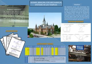
SECTION 8 - RACKING (BRACING) AND SHEAR FORCES STUDENT HANDOUT.

E N D
SECTION 8 -RACKING (BRACING)AND SHEAR FORCESSTUDENTHANDOUT AS 1684 SECTION 8 - RACKING AND SHEAR FORCES
The wind forces are transmitted to the ceiling diaphragm from the walls and also the roof. They are then transferred through the ceiling diaphragm to the bracing walls that transmit them to the floor structure, foundations and then into the ground. With ceiling diaphragm Without ceiling diaphragm AS 1684 SECTION 8 - RACKING AND SHEAR FORCES
As indicated by Figures 8.2 (A) and Note 1, the area of an elevation includes only the top half of the wall. Note: 1 - h = half the height of the wall (half of the floor to ceiling height). This is the area used to calculate single or upper storey bracing Ceiling diaphragm Floor Slab AS 1684 SECTION 8 - RACKING AND SHEAR FORCES
Note 3 of Figures 8.2 (A, B & C) pg 113 states The area of elevation of the triangular portion of eaves overhang up to 1000 mm wide may be ignored in the determination of area of elevation. Area of Elevation AS 1684 SECTION 8 - RACKING AND SHEAR FORCES
When wind flows over a building it applies different pressures (forces) on a flat vertical wall to that on the sloping roof surface. Pressure on roof - 0.77 kPa* Pressure on wall - 1.10 kPa* * These values are indicative only and will vary with roof pitch, building height to depth ratio etc. The tables need to know the ratio between how much roof area the wind ‘sees’ as opposed to how much wall area the wind ‘sees’. The building width and roof pitch will establish this ratio. AS 1684 SECTION 8 - RACKING AND SHEAR FORCES
8.3.4 Racking force(pg 116) The total racking force, in kN, shall be calculated as follows: Projected area of elevation (m2) Lateral wind pressure (kPa) Total racking force x = The racking force shall be calculated for both directions (long and short sides) of the building AS 1684 SECTION 8 - RACKING AND SHEAR FORCES
Ceiling diaphragm Floor diaphragm As indicated by Figures 8.2 (B) and Note 1, the area of an elevation For lower storey of two storey section h = half the height of the lower storey (i.e. lower storey floor to lower storey ceiling) This is the area used to calculate lower storey bracing AS 1684 SECTION 8 - RACKING AND SHEAR FORCES
Determine the wind classification • Determine the wind pressure • Determine area of elevation • Calculate racking force AS 1684 SECTION 8 - RACKING AND SHEAR FORCES
Design Bracing system for walls • Check even distribution and spacing • Check connection of bracing to roof/ceilings and floors AS 1684 SECTION 8 - RACKING AND SHEAR FORCES