Download
1 / 34
340 likes | 370 Views
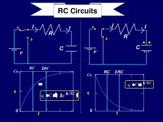
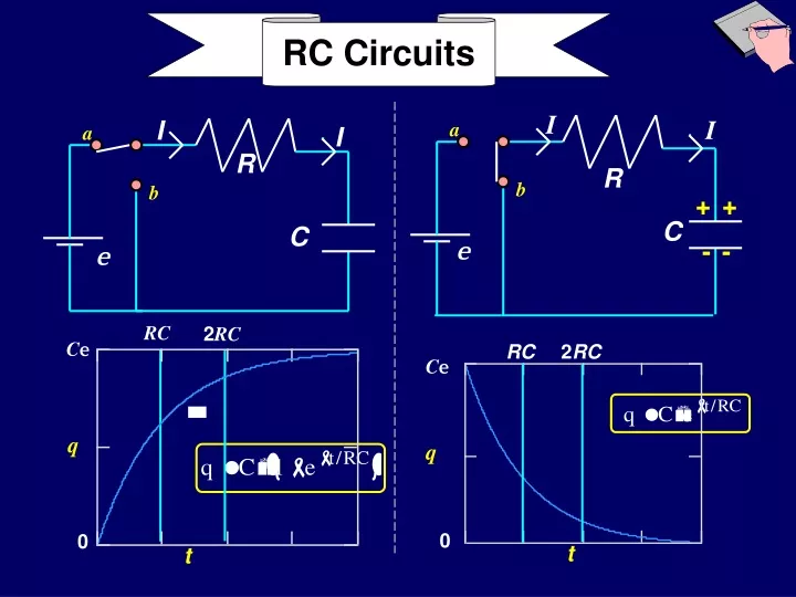
I. I. I. a. I. a. R. R. b. b. +. +. C. C. e. -. -. e. RC Circuits. RC. 2 RC. C e. RC. 2 RC. C e. q. q. 0. 0. t. t. RC Circuits. Calculate Charging of Capacitor through a Resistor Calculate Discharging of Capacitor through a Resistor. I. I. R.

E N D
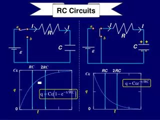
I I I a I a R R b b + + C C e - - e RC Circuits RC 2RC Ce RC 2RC Ce q q 0 0 t t
RC Circuits • Calculate Charging of Capacitor through a Resistor • Calculate Discharging of Capacitor through a Resistor
I I R Let’s try to add a Capacitor to our simple circuit Recall voltage “drop” on C? C e Consider that and substitute. Now eqn has only “Q”. KVL gives Differential Equation ! More complex now… Write KVL: What’s wrong here?
The Big Idea • Previously: • Analysis of multi-loop circuits with batteries and resistors. • Main Feature: Currents are attained instantaneously and do not vary with time!! • Now: • Just added a capacitor to the circuit. • What changes?? • KVL yields a differential equation with a term proportional to Q and a term proportional to • I = dQ/dt.
The Big Idea • Physically, what’s happening is that the final charge cannot be placed on a capacitor instantly. • Initially, the voltage drop across an uncharged capacitor = 0 because the charge on it is zero ! (V=Q/C) • As current starts to flow, charge builds up on the capacitor, the voltage drop is proportional to this charge and increases; it then becomes more difficult to add more charge so the current slows
I I a R b C e Would it matter where R is placed in the loop?? RC Circuits(Time-varying currents) • Charge capacitor: • Cinitially uncharged; connect switch toaat t=0 • Calculate current and • charge as function of time. • • Loop theorem Þ • Convert to differential equation for Q: No!
I I a R b C e Note that this solution incorporates the boundary conditions: ! RC Circuits(Time-varying currents) • Charge capacitor: • • Solution: • Check that it is a solution:
I • Charge capacitor: I a R b C e Þ • Conclusion: • Capacitor reaches its final charge(Q=Ce ) exponentially with time constant t = RC. • Current decays from max (=e /R) with same time constant. RC Circuits(Time-varying currents) • Current is found from differentiation:
Charge on C Max = Ce 63% Max at t=RC Current Max =e /R 37% Max at t=RC Charging Capacitor RC 2RC Ce Q 0 t e /R I 0 t
I I a R b + + C e - - RC Circuits (Time-varying currents) • Discharge capacitor: • C initially charged with Q=Ce • Connect switch to batt=0. • Calculate current and charge as function of time. • Loop theorem • Convert to differential equation forQ:
I I a R b + + C e - - Q(t)must be an exponential function of the form: Therefore, where From initial condition, Q(0)= Q0, we get: Discharging Capacitor • The capacitor is initially fully charged, Q= Q0. Att = 0 the switch is thrown from position a to position b in the circuit shown. • From KVL:
I I • Discharge capacitor: a R b + + C • Guess solution: e - - e -t/RC Q = C e Note that this “guess” incorporates the boundary conditions: Þ ! dQ Q - - t / RC t / RC e e + = - e + e = R 0 dt C RC Circuits(Time-varying currents) • Check that it is a solution:
I I • Discharge capacitor: a -t/RC R e e Q = C b + + C e - - • Current is found from differentiation: Þ • Conclusion: • Capacitor discharges exponentially with time constant t = RC • Current decays from initial max value(= -e/R)with same time constant Minus sign: original definition of current “I” direction RC Circuits(Time-varying currents)
e -t/RC Q = C e zero 0 Current Max= -e/R 37%Max att=RC I -e /R Discharging Capacitor RC 2RC Ce Charge on C Max = Ce 37% Max at t=RC Q 0 t t
e -t/RC Q = C e 0 I -e /R Charging Discharging RC RC 2RC 2RC Ce Ce Q Q 0 0 t t e /R I 0 t t
Behavior of Capacitors • Charging • Initially, the capacitor behaves like a wire. • After a long time, the capacitor behaves like an open switch. • Discharging • Initially, the capacitor behaves like a battery. • After a long time, the capacitor behaves like a wire.
(c)I0+ = 2e /R (b)I0+ = e /2R (a)I0+ = 0 2B • What is the value of the current I¥ after a very long time? (c)I¥ > 2e /R (b)I¥ = e /2R (a)I¥ = 0 Lecture 10, ACT 2 • At t=0 the switch is thrown from position b to position a in the circuit shown: The capacitor is initially uncharged. • What is the value of the current I0+ just after the switch is thrown? 2A a I I R b C e R
I a I R b C e (c)I0+ = 2e /R (b)I0+= e /2R (a)I0+ = 0 R Lecture 10, ACT 2 • At t=0 the switch is thrown from position b to position a in the circuit shown: The capacitor is initially uncharged. • What is the value of the current I0+ just after the switch is thrown? 2A • Just after the switch is thrown, the capacitor still has no charge, therefore the voltage drop across the capacitor = 0! • Applying KVL to the loop at t=0+, e-IR - 0 -IR = 0 ÞI = e /2R
I a I R b C e (c)I0+ = 2e /R (b)I0+ = e /2R (a)I0+ = 0 R 2B • What is the value of the current I¥ after a very long time? (c)I¥ > 2e /R (b)I¥ = e /2R (a)I¥ = 0 Lecture 10, ACT 2 • At t=0 the switch is thrown from position b to position a in the circuit shown: The capacitor is initially uncharged. • What is the value of the current I0+ just after the switch is thrown? 2A • The key here is to realize that as the current continues to flow, the charge on the capacitor continues to grow. • As the charge on the capacitor continues to grow, the voltage across the capacitor will increase. • The voltage across the capacitor is limited to e; the current goes to 0.
Preflight 11: E The capacitor is initially uncharged, and the two switches are open. 3) What is the voltage across the capacitor immediately after switch S1 is closed? a) Vc = 0 b) Vc = E c) Vc = 1/2 E 4) Find the voltage across the capacitor after the switch has been closed for a very long time. a) Vc = 0 b) Vc = E c) Vc = 1/2 E
Initially:Q = 0 VC = 0 I = E/(2R) After a long time: VC = EQ = E C I = 0
Preflight 11: E 6) After being closed a long time, switch 1 is opened and switch 2 is closed. What is the current through the right resistor immediately after the switch 2 is closed? a) IR= 0 b) IR=E/(3R) c) IR=E/(2R) d) IR=E/R
After C is fully charged, S1 is opened and S2 is closed. Now, the battery and the resistor 2R are disconnected from the circuit. So we now have a different circuit. Since C is fully charged, VC = E. Initially, C acts like a battery, and I = VC/R.
(c) Q2 > 2Q1 (b) Q2 = 2Q1 (a) Q2 < 2Q1 • The point of this ACT is to test your understanding of the exact time dependence of the charging of the capacitor. • Charge increases according to: • So the question is: how does this charge increase differ from a linear increase? 2Q1 Q2 • From the graph at the right, it is clear that the charge increase is not as fast as linear. • In fact the rate of increase is just proportional to the current(dQ/dt)which decreases with time. • Therefore, Q2 < 2Q1. Q1 Q t 2t Lecture 11, ACT 1 a I I • At t=0 the switch is thrown from positionb to position ain the circuit shown: The capacitor is initially uncharged. • At time t=t1=t, the charge Q1 on the capacitor is (1-1/e) of its asymptotic charge Qf=Ce. • What is the relation between Q1 and Q2 , the charge on the capacitor at timet=t2=2t ? R b e C R
Preflight 11: The two circuits shown below contain identical fully charged capacitors att=0. Circuit 2 has twice as much resistance as circuit 1. 8) Compare the charge on the two capacitors a short time after t = 0 a) Q1 > Q2 b) Q1 = Q2 c) Q1 < Q2
Initially, the charges on the two capacitors are the same. But the two circuits have different time constants: t1 = RC and t2 = 2RC.Since t2 > t1it takes circuit 2 longer to discharge its capacitor. Therefore, at any given time, the charge on capacitor is bigger than that on capacitor 1.
(c) (b) (a) Lecture 11, ACT 2 • At t=0 the switch is connected to positiona in the circuit shown: The capacitor is initially uncharged. • At t = t0, the switch is thrown from position a to position b. • Which of the following graphs best represents the time dependence of the charge on C? a b R 2R C e • For 0 < t < t0, the capacitor is charging with time constantt = RC • Fort > t0,the capacitor is discharging with time constantt = 2RC • (a) has equal charging and discharging time constants • (b) has a larger dischargingtthan a chargingt • (c) has a smallerdischargingtthan a charging t
I1 I2 I3 A very interesting RC circuit e C R2 R1 First consider the short and long term behavior of this circuit. • Short term behavior: • Initially the capacitor acts like an ideal wire. Hence, • and • Long term behavior: • Exercise for the student!!
Preflight 11: The circuit below contains a battery, a switch, a capacitor and two resistors 10) Find the current through R1 after the switch has been closed for a long time. a) I1 = 0 b) I1 = E/R1 c) I1 = E/(R1+ R2)
After the switch is closed for a long time ….. The capacitor will be fully charged, and I3 = 0. (The capacitor acts like an open switch). So, I1 = I2, and we have a one-loop circuit with two resistors in series, hence I1 = E/(R1+R2) What is voltage across C after a long time? Cis in parallel withR2 !! VC = I1R2 = E R2/(R1+R2) < E
Loop 2 • Loop 1: I1 I2 I3 Loop 1 e C • Loop 2: R2 • Node: R1 • EliminateI1 inL1 and L2 using Node equation: eliminate I2 from this • Loop 1: • Loop 2: • Final differential eqn: Very interesting RC circuit continued
Loop 2 • Final differential eqn: I1 I2 I3 Loop 1 e C R2 R1 time constant: t parallel combination of R1 and R2 Very interesting RC circuitcontinued • Try solution of the form: • and plug into ODE to get parameters A and τ • Obtain results that agree with initial and final conditions:
Loop 2 I1 I2 I3 Loop 1 e C R2 R1 I2 e C R2 R1 Different time constant for discharging Very interesting RC circuitcontinued • What about discharging? • Open the switch... • Loop 1 and Loop 2 do not exist! • I2is only current • only one loop • start atxmarks the spot...
Reading assignment: Ch. 28.1-2, 28.4 Examples: 28.1,4,5 and 6 Summary • Kirchoff’s Laws apply to time dependent circuitsthey give differential equations! • Exponential solutions • from form of differential equation • time constantt = RC • whatR, whatC??You must analyze the problem! • seriesRC charging solution • seriesRCdischarging solution e e -t/RC Q = C Next time: Start Magnetism