Download
1 / 30
300 likes | 441 Views
The Design of Barrel Electromagnetic Calorimeter (BEMC) October 13 2001. ---Lu Jun-guang. Barrel Electromagnetic Calorimeter (BEMC). 1. General Consideration 2. Choice of Calorimeter Type 3. How to arrange L3 BGO crystals

E N D
The Design of Barrel Electromagnetic Calorimeter (BEMC)October 13 2001 ---Lu Jun-guang
Barrel Electromagnetic Calorimeter (BEMC) 1. General Consideration 2. Choice of Calorimeter Type 3. How to arrange L3 BGO crystals 4. Structure of BEMC 5. Readout 6. Calibration and monitoring 7. MC Simulation 8. Expected Performance 9. R&D plan, schedule 10. Summary
1. General Consideration Excellent photon energy and angular resolution, coupled with good low energy detection efficiency is essential to the physics of the BESIII General physics requirements • Energy response region: 10 MeV to 2 GeV. The key energy region< 500MeV • Reconstruction of π0 and η • Contributes to e/πand e/μseparation • Provide neutral energy trigger
2. Choice of Calorimeter Type • Comparison of the scintillating fiber calorimeter and BGO crystal calorimeter options, L3-BGO crystals have been selected to use as the BESIII calorimeter: ☆ a very big benefit for energy and angular resolution at BGO crystal option. • Energy resolution: % /√E (GeV) 2.5 (BGO)6 (scint_fiber) • Spatial resolution : σ,~ /√E (GeV) 0.3cm (BGO)1cm (scint_fiber)
3.How to use L3 BGO crystals * L3 BGO crystals Rin(barrel) ~52 cm, Lin(barrel) ~100 cm 7680 (barrel) + 3072 (end-cap) 2cm x 2cm, 2.6x2.6~2.9x2.9 cm2 Crystal length : 24 cm ( 22X0 ) Density 7.13 g/cm3 Radiation length 1.12 cm dE/dX 9 MeV/cm dE/E 2%/√E(GeV)
a.Cut BGO crystals (10752)22 X0: ~13X0 (14cm) + 8.5 X0(9.5cm)making new piece by gluing: 9.5cm + 4.5 cm=14cm8800 (front face: ~2.42cm2 ) / L: 14 cm 1952 (front face: ~2.02cm2 ) / L: 14 cm 8800 (front face: ~2.02cm2 ) / L: 9.5 cm 1952 (front face: ~2.42cm2 ) / L: 9.5 cm 2x 1952=3904 / L: 4.5 cm 2x192=384 / L: 4.5 cmb. produce new BGO crystal piece:4512/L: 4.5cm ~130 kcc total crystals: 8800 (~2.42cm2)+10560(~2.02cm2) =19360
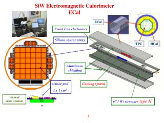
4.Structure of BEMC *to rebuilt a barrel EMC: Rin ~77cm , Lin ~194cm cosθ=0.78 44 rings (240 piece: front face~2.02cm2) 44 rings (200 piece: front face~2.42cm2) 10560(~2.02cm2) + 8800 (~2.42cm2)=19360 *grinding and polishing of the BGO crystals Insert one newly machined crystal for every two old crystals in both θ andφ
5. Readout • Two photodiodes per crystal in L3 Hamamatsu PD-S2662, Ssens=20x7.5mm2 Total PDs: 2x18160=36320 piece (S2662) 1200 piece (S3950/Ssens=10x10mm2) • Two charge amplifier and one main amplifier Total electronics: 19360 chs.
6. Calibration and monitoring • Different response of crystals due to: *different crystal gluing, shape, quality *different PD and its coupling *different radiation damage • Several effects can change the response of the calorimeter: radiation damage, temperature variations, optical changes of the crystal-PD glue joint, variations of electronics.
BGO crystal scanning using γ source Cs137 (662 KeV) For the glued crystal, light output reduced by ~25%, energy resolution worsened by ~30%
Calibration methods *single crystal (before assembly) # optical testing # radiation source scan # cosmic rays testing (after gluing PD) *whole calorimeter(after assembly) # try to use a γ ( >4 MeV) source # test beam # cosmic rays testing *In-situ Calibration # light pulser (Xenon -optical fiber) monitoring # temperature monitoring # electronic calibration # physics processes (e+e-→ββ,γγ,μμ, γββ, and πo )
7. MC Simulation * Energy resolution: 14cm length (~13X0) Eγ : 0.1~1.5 GeV, The fluctuation of deposited energy (σ) is from 10% to 3%. * Energy leakage: 1~5% * Transverse spread of shower Eγ=200MeV, shown the transversal spread is within 5 pieces of BGO crystals. * The deposited energy of π and μ * The deposited energy of π and e
8. Expected Performance • Energy resolution:2.5~3%/√E(GeV) • Spatial resolution: ,≤ 3 mm/√E(GeV) • 2γ angular resolution:2= 50 mr Mass of 0 →γγ: 0= 6 MeV • Minimum energy of the detectable: Eγ=10 MeV • Solid angle:73%×4π
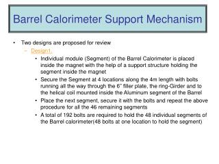
9. R&D and schedule • Machining of the BGO crystals * BGO crystal arrangement * how to cut, grind and polish crystals • Mechanical support of crystals * one or several crystals for each cell * material of the wall: carbon fiber or Al? • Hardware systems for calibration and monitoring * xenon light pulser system * temperature monitoring * γ source testing * Test beam
Schedule of Project 2001/6——2002/12: shipping and R&D2003/1——2003/12: machining and crystal testing crystal cutting, grinding, polishing, gluing and painting * measuring properties of the BGO crystal* manufacture of mechanical support structure * production of the preamplifier 2004/1——2004/12:* crystals machining continue* crystal assembly and testing with readout modules 2005/1—2005/6 *inserting the crystal elements into the support system * testing the whole crystal calorimeter *assembling the Calorimeter to BESⅢspectrometer 2005/6: Testing and tuning the BESⅢ spectrometer
Preliminary Cost Estimate L3 BGO crystals 25.50 M¥ Supplemental new BGO crystals ~130 kcm3 11.00 M¥ Silicon photodiodes 20000 pieces 3.40 M¥ BGO crystal cutting, grinding, polishing 3.00 M¥ Structure of the crystal elements 1.00 M¥ Monitor system (xenon –light and temperature) 1.20 M¥ Support product and assembly equipment 5.00 M¥ Measurement equipment (normal and cosmic ray test system) 1.20 M¥ Total 51.30 M¥
10. Summary • A basic design of BEMC is to use L3 BGO crystals after cutting, grinding and polishing, with nearly 13X0 in length • Building BEMC with a size: R~77cm, L~ 194cm • Readout: adopt two PD S2662 in each crystal,total channels: 19360 • Single crystal calibration will adopt γ source and Xenon flusher for monitoring • MC: E/E ≤ 3%/√E, Mπ0 ~ 6 MeV • Expected performance: E/E ≤ 3%/√E , ,≤ 3mm/√E Thanks