Download
1 / 58
731 likes | 1.34k Views
Chapter 3 – Hydraulic Pumps. Topics Pump Flow and Pressure Pump Drive Torque and Power Pump Efficiency Pump Types Pressure Compensated Pumps Cavitation and Aeration Symbols Pump Specifications. Hydraulic Power Unit. Relief Valve. Basic Pump.

E N D
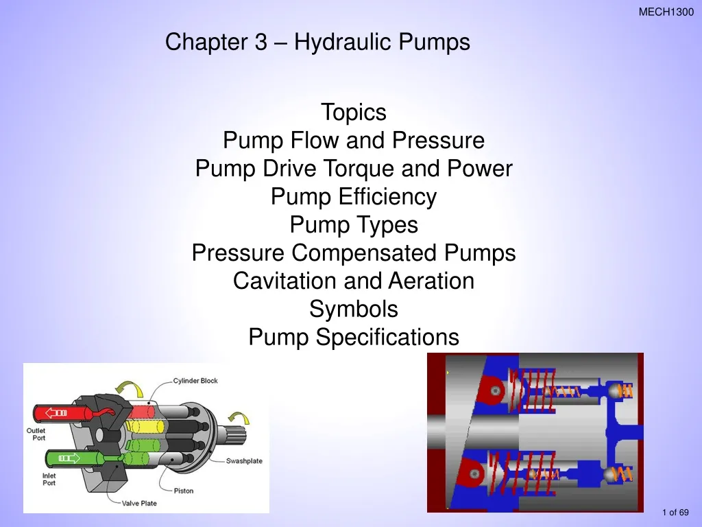
Chapter 3 – Hydraulic Pumps Topics Pump Flow and Pressure Pump Drive Torque and Power Pump Efficiency Pump Types Pressure Compensated Pumps Cavitation and Aeration Symbols Pump Specifications
Hydraulic Power Unit Relief Valve
Basic Pump • The basic operating principle that moves fluid through a pump is similar in all pumps • Enlarging the volume of a chamber allows fluid to enter the pump • Reducing the chamber volume moves fluid to the system • Inlet and discharge valves or ports control fluid movement through the pump
How Pumps Work • In a rotary pump, the pumping action is produced by revolving components • In a reciprocating pump, the rotating motion of the pump input shaft is changed to reciprocating motion, which then produces the pumping action
Basic Pump • Increasing the size of the pumping chamber moves fluid into the pump
Basic Pump • Reducing the size of the pumping chamber forces fluid into the system
Basic Pump • The maximum pressure developed in a hydraulic system is determined by: • Resistance to fluid flow in the system • Force the prime mover can exert • The output flow rate of a hydraulic pump is determined by: • Volume of the pumping chamber • Operating speed of the prime mover
Pressure • Path of least resistance: • If there is no force (load) on a cylinder there is no pump pressure! • What will happen to cylinders A & B when power is applied to the pump? • Cylinder A • Dia. = 4” with a load of 2000 lbs • Cylinder B • Dia. = 8” with a load of 4000 lbs Cylinder A Cylinder B Pump
Cylinder A • Dia. = 4” with a load of 2000 lbs • Area = 12.566 in2 • P= F/A = 159.2 psi Cylinder A Cylinder B • Cylinder B • Dia. = 8” with a load of 4000 lbs • Area = 50.27 in2 • P= F/A = 79.57 psi Cylinder B moves first until it is fully extended and then Cylinder A extends Pump
Displacement – The volume of fluid that is discharged per cycle. Cycle – One revolution of the pump shaft. Theoretical Flow Rate -
EX – A pump has a displacement of and is driven at 1800rpm. What is the theoretical flow rate?
Pump Drive and Torque Power Prime mover supplies input power to the pump by driving the pump shaft at a rotational speed. Pressure on the pump resists rotation. Prime mover must generate enough torque to turn the shaft against the resistance.
Ex: A hydraulic pump with a displacement of is selected for a system that will operate at a maximum pressure of 5000 psi. What is the required drive torque?
Ex: A hydraulic pump with a displacement of is selected for a system that will operate at a maximum pressure of 40,000kPa. What is the required drive torque? Convert to
EX: An electric motor drives a pump at 1500 rpm with a torque of 300 . What is the power input to this pump?
Pump Efficiency Ratio of actual flow rate to theoretical flow rate Volumetric efficiency:
EX: A pump has a displacement of and a volumetric efficiency of 0.93. If it is driven at 1300 rpm, what will its actual flow rate be?
Overall efficiency Just like regular efficiency – output/input
EX: A pump has and overall efficiency of 0.88 and a flow rate of 40 lpm is to be used in a system that has a maximum operating pressure of 20,000kPa. What is the input power require? Calculate the hydraulic power: Calculate the input power:
Pump Classifications • Hydraulic pumps can be classified using three basic Characteristics: • Displacement • Pumping motion • Fluid delivery characteristics
Displacement Pump • Displacement relates to how the output of the pump reacts to system loads • Positive-displacement pumps produce a constant output per cycle • A non-positive-displacement pump has large internal clearances • Allows fluid slippage in the pump • Results in varying flow output as system load varies
Displacement Pump • Positive-displacement pump
Displacement Pump • Non-positive-displacement pump
Pumping Motion Classifications • The basic pumping motions used in hydraulic pumps are: • Rotary • Gear pumpsare rotary pumps • Reciprocating • Piston pumps are reciprocating pumps Reciprocating piston movement
Fluid Delivery Classifications • Hydraulic pumps are classified as either fixed or variable delivery • Fixed-delivery pumps have pumping chambers with a volume that cannot be changed; the output is the same during each cycle • In variable-delivery designs, chamber geometry may be changed to allow varying flow from the pump
Fluid Delivery Classifications • Gear pumps are fixed-delivery pumps
Fluid Delivery Classifications • Piston pumps may or may not be variable-delivery pumps
Variable Displacement Pumps http://www.mekanizmalar.com/variable_displacement_piston_pump.html
Variable Displacement Pumps http://www.mekanizmalar.com/variable_displacement_piston_pump.html
Pump Selection • When selecting a pump for a circuit, factors that must be considered are: • System operating pressure • Flow rate • Cycle rate • Expected length of service • Environmental conditions • Cost
Pump Design, Operation,and Application • Gear pumps: • positive-displacement, • fixed-delivery, • rotary units • external or internal gear teeth configurations
Pump Design, Operation,and Application • Pumping action of gear pumps results from unmeshing and meshing of the gears • As the gears unmesh in the inlet area, low pressure causes fluid to enter the pump • As the pump rotates, fluid is carried to the pump discharge area • When the gears mesh in the discharge area, fluid is forced out of the pump into the system • Flow outputs from below 1 gpm to 150 gpm • Pressure rating range up to 3000 psi
Pump Design, Operation,and Application • Vane pumps are positive-displacement, fixed or variable delivery, rotary units. • Design is commonly used in industrial applications • Delivery can range up to 75 gpm • Maximum pressure of about 2000 psi
Pump Design, Operation,and Application • Vane pump consists of a slotted rotor, fitted with moveable vanes, that rotates within a cam ring in the pump housing • Rotor is off center in the ring, which creates pumping chambers that vary in volume as the pump rotates • As chamber volume increases, pressure decreases, bringing fluid into the pump • As volume decreases, fluid is forced out into the system
Pump Design, Operation,and Application • Piston pumps: • positive-displacement, fixed- or variable-delivery, reciprocating units • provide high volumetric efficiency (90%), • high operating pressure (10,000 psi or higher), • high-speed operation
Pump Design, Operation,and Application • A basic piston pump consists of a housing that supports a pumping mechanism and a motion-converting mechanism • Pumping mechanism is a block containing cylinders fitted with pistons and valves • Motion converter changes rotary to reciprocating motion via cams, eccentric ring, swash plate, or bent-axis designs • Rotating the pump shaft causes piston movement that pumps the fluid
Pump Design, Operation,and Application • Piston pump classification is based on the relationship between the axes of the power input shaft and piston motion • Axial • Inline • Bent axis
Pump Design, Operation,and Application • Piston pump classification is based on the relationship between the axes of the power input shaft and piston motion • Radial • have the highest continuous operating pressure capability of any of the pumps regularly used in hydraulic systems • are available with operating pressure ratings in the 10,000 psi range
Pump Design, Operation,and Application • A stationary-cylinder radial-piston pump
Pump Design, Operation,and Application Reciprocating Radial
Pump Design, Operation,and Application • Screw pumps have pumping elements that consist of one, two, or three rotating screws • the screws rotate, fluid is trapped and carried along to the discharge of the pump • screw pumps operate at a very low noise level
Additional Design Features of Pumps • A dual-pump design Sauer-Danfoss, Ames, IA