Download
1 / 29
320 likes | 558 Views
Asynchronous Machines. Used slides from Mitch Thornton and Prof. Hintz. Reduce States. State Assignment. Flip-Flop or Latch Selection. Asynchronous FSM. Fundamental Mode Assumption Only one input can change at a time

E N D
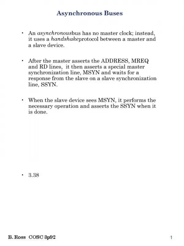
Asynchronous Machines • Used slides from Mitch Thornton and Prof. Hintz
Reduce States State Assignment Flip-Flop or Latch Selection
Asynchronous FSM Fundamental Mode Assumption • Only one inputcan change at a time • Analysis too complicated if multiple inputs are allowed to change simultaneously • Circuit must be allowed to settle to its final value before an input is allowed to change • Behavior is unpredictable (nondeterministic) if circuit not allowed to settle
Asynch. Design Difficulties Delay in Feedback Path • Not reproducible from implementation to implementation • Variable • may be temperature or electrical parameter dependent within the same device • Analog • not known exactly Tell my stories how I worked with asynchronous machines in 1968
Stable State • PS = present state • NS = next state • PS = NS = Stability • Machine may pass through none or more intermediate states on the way to a stable state • Desired behavior since only time delay separates PS from NS • Oscillation • Machine never stabilizes in a single state
Races • A Race Occurs in a Transition From One State to the Next When More Than One Next State Variables Changes in Response to a Change in an Input • Slight Environment Differences Can Cause Different State Transitions to Occur • Supply voltage • Temperature, etc.
PS 01 11 00 if Y1 changes first if Y2 changes first 10 desired NS Races
Types of Races • Non-Critical • Machine stabilizes in desired state, but may transition through other states on the way • Critical • Machine does not stabilize in the desired state
01 11 00 10 00 critical race Races PS if Y2 changes first if Y1 changes first desired NS non- critical race
Asynchronous FSM Benefits • Fastest FSM • Economical • No need for clock generator • Output Changes When Signals Change, Not When Clock Occurs • Data Can Be Passed Between Two Circuits Which Are Not Synchronized • In some technologies, like quantum, clock is just not possible to exist, no clocks in live organisms.
Asynchronous FSM Example input next state present state y1 y2
Next State Variables You can analyze this machine at home
Asynchronous State Tables States are either Stable or Unstable. Stable states encircled with symbol. Oscillations occur if all states are unstable for an input value. Total Stateis a pair (x, Qi)
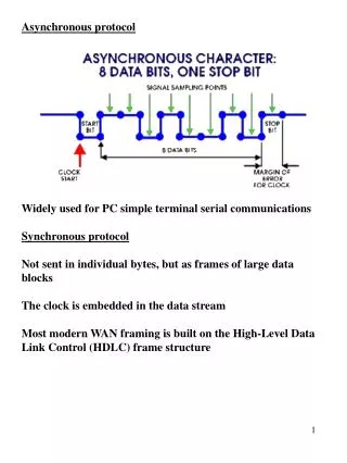
Constraints on Asynchronous Networks If the next input change occurs before the previous ones effects are fed back to the input, the machine may not function correctly. Thus, constraints are needed to insure proper operation. Fundamental Mode – Input changes only when the machine is in a stable state. Normal Fundamental Mode – A single input change occurring when the machine is in a stable state produces a single output change.
Example 8.4 Find state table for network Let Q0 be state when y1 = 0 and Q1 be state when y1 = 1. z1z2
Example 8.5 Analyze circuit withfundamental model Ask student to do this analysis
Example 8.5 Analyze circuit without fundamental mode
Example 8.6 Design the network for the given state table using SR-latches Use state assignment
Example 8.6 (Continued) Use S when state variable must change from 0 to 1 Use R when state variable must change from 1 to 0 Use s when state variable remains 1 Use r when state variable remains 0
Example 8.7 – D Flip-Flop Design the circuit from the state table using SR-latches
Example 8.8 Derive the state table from the circuit 1’s where Set and (present state is 1 and not R)
Race Conditions - Example 8.9 Race Condition – when two or more variable change at a time Critical Race – final state dependent on order in which the state variables change Input x1,x2 10 00 10, 00, 01 ok 10, 11, 01 not ok.
Q3 Q2 Avoiding Race State Adjacency Diagram State Adjacency Diagram Q0 Q1 Impossible to have hamming distance of 1 between all adjacent states. Must add states. Table from previous page
Asynchronous Machine Hazards Steady-State Hazards– Occurs when a sequential network goes to an erroneous state due to gate delay. Static-1 Hazard In (01, Q1) consider input change (00) (01) y1= x1x2 +x1 y1y2+x2 y1y2 y2 = x1x2 +x2 y2+x1y1
Steady-State Hazards Elimination of Static-1 Hazard y1= x1x2 +x1 y1y2+x2 y1y2 y2 = x1x2 +x2 y2+x1y1 +x1 y2
Hazard Example Feedback Sequential Implementation Maps resulting from State Table 8.5, Example 8.7
Essential Hazard • Essential Hazard– • Erroneous sequential operation that cannot be eliminated without controlling delays in the circuit. • Not affected by elimination of combinational logic hazards.
Essential Hazard Example Caused by multiple paths for x Starting in stable stateQ2 with input 0 1 Slow Students should complete this example in class, on Friday or at home