Download
1 / 84
920 likes | 1.28k Views
Solution. Feb. 15. 2007 Samsung Electronics. INDEX. Solution Lineup Wired remote controller 7-day scheduler Interface module Centralized control Power distribution DMS S-Net 2 Plus S-Net I S-Net 3 S-Net mini. Domestic. GHP. ERV. 1. Solution Lineup. BAC. MIM-B02.

E N D
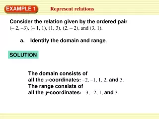
Solution Feb. 15. 2007 Samsung Electronics
INDEX • Solution Lineup • Wired remote controller • 7-day scheduler • Interface module • Centralized control • Power distribution • DMS • S-Net 2 Plus • S-Net I • S-Net 3 • S-Net mini
Domestic GHP ERV 1. • Solution Lineup BAC MIM-B02 FJM MST-P3P MST-S1P MWR-TH01 MIM-B04A MCM-A202 Mini DVM S-Net mini DVM MST-P1W0 MWR-BS00 MIM-B13 MWR-BS00 DVM Plus MCM-A100 MCM-B102 S-Net mini S-Net mini DVM Plus II MIM-B07 MWR-WS00 MIM-D00 MIM-B12 MIM-B06
Model Image Features • Support COM 1 and COM 2 wiring • RMC address assignment MWR-TH01 • Only support COM 2 wiring • Support 2400 / 9600 bps • Newly designed • Sleep mode, Silent mode, Child lock • Real time clock & 7-day schedule function • Temperature sensor • Service mode (Additional functions) - Indoor unit option code setting function etc. MWR-WS00 2. • Wired remote controller ■ Features
COM 1 Wiring COM 2 Wiring ■ Connection units ■ Connection units • Outdoor unit • Indoor units • Interface module (Key-tag, Lonworks, 485) • Wired remote controller • Power distribution unit • Indoor units • Wired remote controller • 7-day scheduler ■ Old error display (Er XX) ■ Error code display (E XXX) 2. • Wired remote controller ■ Communication channel Dose the outdoor unit support the PLUS protocol? Install on COM 1 Install on COM 2 N Y
12VDC for wired Remote controller COM 1 wiring COM 2 wiring 2. • Wired remote controller ■ Terminal block on the indoor unit
Wired Remote Control (MWR-TH01) Terminal Block Communication Line Red Blue White Black 12VDC Power Supply 2. • Wired remote controller ■ COM 1 wiring of wired remote controller Only CAC non-inverter model supports COM 1 wiring.
Wired R/C Enable/Disable Indoor Unit Option Setting I/M Enable/Disable Outdoor Unit RMC Address Main Address Main 0 Main 1 Main 2 RMC 0 RMC 1 RMC 2 MWR-TH01 RMC 0 RMC 1 RMC 2 2. • Wired remote controller ■ COM 1 wiring of wired remote controller
2. • Wired remote controller ■ COM 2 wiring of wired remote controller Wired Remote Control (MWR-TH01 / WS00) Terminal Block 12VDC Power Supply White Black Red Blue Communication Line (Non-polarity)
SW1 SW4 SW5 SW8 Address switch DS01 DS02 DS03 DS02 DS01 2. • Wired remote controller ■ Option switch setting (MWR-TH01)
2. • Wired remote controller ■ Assign RMC address (MWR-TH01 COM 2 wiring) SW 5 ‘OFF’ • Set SW 5 of DS02 switch on the wired remote controller PCB to ‘OFF’. • Press the ‘Mode’ button and ‘Fan speed’ button in front of thewired remote control simultaneously for more than5 seconds. Enter ‘Group address setting mode’ • Wired remote controller LCD displays main address and RMC (Group) address and changes to the “Indoor unit group address setting mode”. • Adjust RMC address using “Up” and “Down” buttons. Change RMC • Press the “Operation” button to select the required group address. Then, the group address display flickers and changes. RMC change • Press the button once to set the selected group address with the ‘beep’ sound. Change confirm • Press the button again to quit the setting mode and enter the operation • mode. Operation mode
2. • Wired remote controller ■ Option switch setting (MWR-WS00) • After adding / removing indoor units or indoor unit PCB change, press the “Set” button and “Cancel” button simultaneously for 5 seconds.
2. • Wired remote controller ■ Service mode (MWR-WS00) • If the option switch SW8 is set to ‘OFF’, the above service modes can be only monitored. Set the option switch SW8 to ‘ON’ to set the above service modes.
2. • Wired remote controller ■ COM 2 basic wiring
2. • Wired remote controller ■ 2 Wired remote controller wiring Max 2 Wired remote controller
2. • Wired remote controller ■ Group control using wired remote controller Max 16 Indoor units
2. • Wired remote controller ■ Group control using 2 wired remote controllers Max 16 Indoor units Max 2 Wired remote controller
3. • 7-day scheduler ■ Features Model Image Features • Weekly schedule for 1 or 16 groups • Can interface with wired remote controller or centralized controller • Can skip schedule on specified date MWR-BS00 With MWR-TH00 / MWR-TH01 With MCM-A201 • Connects to COM 2 wiring (F3 / F4) • Connects to R1 / R2 communication port • Does not support individual group schedules • Controls all indoor units under centralized controller
3. • 7-day scheduler ■ Wired remote controller / 7-day scheduler SW 2 On : Disable the On/Off button on the wired remote controller
3. • 7-day scheduler ■ Wired remote controller / 7-day scheduler (Group control) Max 16 Indoor units SW 2 On : Disable the On/Off button on the wired remote controller
3. • 7-day scheduler ■ 2 Wired remote controller / 7-day scheduler SW 2 On : Disable the On/Off button on the wired remote controller
3. • 7-day scheduler ■ Centralized control using 7-day scheduler In case of mini-DVM & DVM Plus II, this combination is impossible . Max 16 Interface modules Max 16 Interface modules
Model Image Features • 485 communication interface module • 2400 / 9600 bps auto detection • BAC, DVM, FJM, DVM Plus series MIM-B04A • 485 communication interface module • 2400 / 9600 bps auto detection • Support earlier version include DVM Plus II MIM-B13 • Key-tag interface module • Be used in hotel where the A/C need to turn off if vacant MIM-B02 • Lonworks interface module • BMS connection using Lonworks protocol MIM-B07 4. • Interface module ■ Features
MIM-B14 If two indoor units are installed in the room If only one indoor unit is installed in the room Wire according to the main address of the indoor unit. 4. • Interface module ■ Key-tag interface module (MIM-B02) • Be widely used in hotels where the A/C needs to turn off if vacant. • Can be used with the 485 interface module simultaneously only on selected outdoor units. (RVMH060GDM3, RVMH100GCM3, RVMR100GCM0) • From DVM Plus II Indoor units, MIM-B14 (External control interface module) has the Key-Tag function.
4. • Interface module ■ Key-tag I/M Option switch setting (MIM-B02) Initial event control • Only available in external control mode ( SW 3 Off ) • This function is used for indoor units without breakout recovery function. • If power reset occurs, an event signal is generated to recover operation status of indoor unit after checking the external contact status. • If the indoor units were ON before power reset, an event signal is generated to turn on the indoor units after power reset. If the indoor units OFF before power reset, they remain OFF after power reset.
4. • Interface module ■ Key-tag interface function Off Control by contact status HIGH(SHORT) Contact Status LOW(OPEN) ON OFF Command OFF Command Command Indoor Operation 1 2 3 4 Working Working Stop Stop DS01 On event by other controller HIGH(SHORT) LOW(OPEN) Contact Status ON OFF Command OFF Command Command Indoor Operation 1 2 3 4 Working Working Stop Stop DS01 On event by other controller
4. • Interface module ■ Key-tag interface function On/Off Control by contact status LOW(OPEN) Power In HIGH(SHORT) Contact Status ON Command ON Command ON OFF Command Command Working Working Indoor Operation 1 2 3 4 Stop Stop DS01 Off event by other controller Power In LOW(OPEN) HIGH(SHORT) Contact Status ON ON Command ON Command OFF Command Command 1 2 3 4 Working Working Indoor Operation Stop Stop DS01 Off event by other controller
4. • Interface module ■ Key-tag interface module wiring Max 16 Indoor units Samsung Scope
4. • Interface module ■ Key-tag interface module / Centralized controller RVMH060GDM3, RVMH100GCM3, RVMR100GCM0 Max 16 Indoor units Samsung Scope
4. • Interface module ■ External control interface module • Control indoor unit by “External contact signal”. (Switch, Timer etc.) • Display “Compressor operation and error status”. • Set DIP switch K11 to “Off” on the indoor unit’s PCS. • Note • 1. Operation is as same as last operation status. • (At first , “Auto mode, Set temp. 24℃, Auto airflow”) • 2. Impossible to connect with wall mounted Indoor units. • (Vivace, Prestige, Premium)
External Signal Operation 4. • Interface module ■ External control interface module (Direct connection) Relay External Signal Signal with power DB39-01263A CN83 DIP S/W K11 : Off PCB of duct type indoor unit
Off Delay Timer Relay Timer setting Push Button Switch Power External Signal CN83 CN81 Supplied by installer Operation DIP S/W K11 : Off 4. • Interface module ■ External control interface module (Timer Delay) MIM-B14 (DB93-04159A) DB39-01263A DB39-01264A
4. • Interface module ■ Lonworks interface module (MIM-B07) MIM-B07 is used to manage DVM air conditioner with other devices using one of BMS open protocol Lonworks.
4. • Interface module ■ Lonworks interface module (MIM-B07) • Lonworks Interface Module • Model Code : MIM-B07 • CPU : Neuron 3150 Smart Transceiver • Communication : RS485 to FTT-10A • FTT-10A 78Kbps • Free topology • Service Pin : Auto-binding • Power Input : DC 12V • Size : 50mm x 80mm • Parallel connection (4 units) Neuron Chip Transceiver
DVMIndoor[12] nviIndoorMode nvoIndoorStatus nviSetTemp nvoRoomTemp nviFanSpeed 4. • Interface module ■ SNVT (Standard Network Variable Type) Configuration
4. • Interface module ■ SNVT (Standard Network Variable Type) Configuration nviIndoorMode nviFanSpeed nviIndoorStatus
A E B D5 D6 D3 C D4 D 4. • Interface module ■ MIM-B07 Installation test • Test using LED 1) D3(Service Pin LED) : Turn on when pushing service pin 2) D4 (Command Status LED) : Command receive on Network (0.2s) 3) D5 (RS485 Tx) : Flicking when data send on RS485 comm. Line (0.06s) 4) D6 (RS485 Rx) : Flicking when data receive on RS485 comm. Line (0.06s) • Function 1) “A” : Service Pin – Use Binding with other Lonworks I/M. 2) “B” : RS485 Comm. connector with DVM Outdoor and indoors. 3) “C” : Power connector (12VDC) from Outdoor units. 4) “D” : Terminal block for FTT-10A (Twisted Pair).
4. • Interface module ■ Lonworks interface module wiring Max 12 Indoor units Samsung Scope Lonworks Lonworks Twisted Pair Power Lon to TPC/IP Router Equipment Ethernet Entrance Light BMS SYSTEM
4. • Interface module ■ Lonworks I/M wiring (More than 12 indoor units) Max 48 Indoor units Max 4 Lonworks interface modules Power source : Install maximum 2 I/M from each outdoor module Samsung Scope Lonworks Lonworks Twisted Pair
5. • Centralized control ■ Features Model Image Features • Use with 7-day scheduler • BAC, DVM, FJM, DVM Plus series MCM-A201 • High speed communication version • Use with 7-day scheduler • Support earlier version include DVM Plus II MCM-A202 • Used with centralized controller • Group control up to 16 indoor groups • Error display function MCM-A100
FRONT VIEW 220V AC Power input N L C2 C1 R2 R1 Function Controller SNET II+ 485 Interface Module 5. • Centralized control ■ Installing the centralized controller (MCM-A202) • LED On equivalent to interface module address at tracking. • Green LED of PCB backside is flickering when communication with interface module. Red LED is flickering when communication with DMS. • If “11” and “15” button press at the same time for 5 seconds, centralized controller is reset.
5. • Centralized control ■ Option switch setting (MCM-A202) Setting error display : Rotated flickering
5. • Centralized control ■ Centralized control level Level Features • No priority level. • Wired and wireless remote controller can be used. 0 • Wired and wireless remote controller are disabled when the indoor unit is stopped by centralized controller. 1 2 • Remote controllers are disabled at all time • The “All ON” button determines stand-by state. When the “All ON” button is pressed, ON-state LED turns on without turning on all the indoor units and the remote controllers are allowed to use. 3
5. • Centralized control ■ Cooling / heating selection switch • If set to “cool”, the indoor units will turn on to the cooling mode. However, this does not mean that heating mode is disabled. • If set to “heat”, the indoor units will turn on to the heating mode. MCM-C200 To prevent cooling/heating mode confusion error on the heatpump outdoor unit, MCM-C200 also can be used.
DC 12V Front Rear V2 V1 C1 C2 DC 12V Communication Line From Centralized Controller 5. • Centralized control ■ Installing the function controller (MCM-A100)
5. • Centralized control ■ Wiring (mini-DVM, DVM, DVM HR : Individual) Max 16 Indoor units ※ Include DVM Plus less than 16 indoor units
5. • Centralized control ■ Wiring (DVM Plus : Individual) From 17 to max 32 Indoor units
5. • Centralized control ■ Wiring (DVM Plus II : Individual) Less than 16 Indoor units Channel 1
5. • Centralized control ■ Wiring (DVM Plus II : Individual) From 17 to max 32 Indoor units Channel 1 Channel 2
5. • Centralized control ■ Wiring (DVM Plus II : Individual) From 33 to max 48 Indoor units Channel 1 Channel 2 Channel 3