Download
1 / 63
680 likes | 1.17k Views
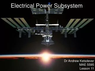
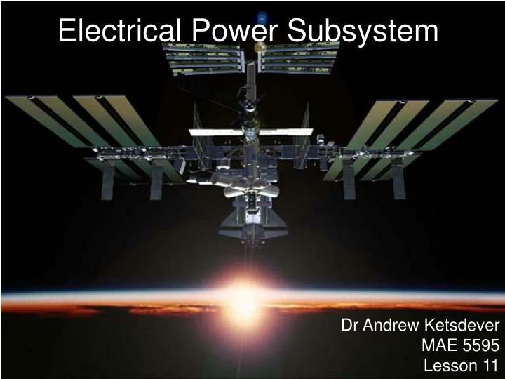
Electrical Power Subsystem. Dr Andrew Ketsdever MAE 5595 Lesson 11. Outline. Electrical Power Subsystem Introduction Types of Power Sources Design Considerations Nuclear Power Nuclear Reactor Radioisotope Thermoelectric Generator (RTG) Solar Arrays Types

E N D
Electrical Power Subsystem Dr Andrew Ketsdever MAE 5595 Lesson 11
Outline • Electrical Power Subsystem • Introduction • Types of Power Sources • Design Considerations • Nuclear Power • Nuclear Reactor • Radioisotope Thermoelectric Generator (RTG) • Solar Arrays • Types • Sample Calculation: Array sizing • Batteries • Types • Sample Calculation: Battery storage • Depth of Discharge • Degradation of Solar Arrays • Radiation
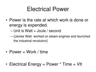
Power Sources • Chemical: Battery, Fuel Cell • Converts chemical energy into electrical power • Stored energy • Chemical reaction • Solar: Photovoltaic • Coverts solar radiation into electrical power • Nuclear: Fission • Coverts nuclear fission energy into electrical power through conversion of heat • Dyanamic: Heat energy • Stirling, Rankine, Brayton cycles (15-35% efficient) • We will mainly talk about solar array and battery systems
Power Sources From Space Vehicle Design, by Griffin and French
Nuclear Reactor • Reflector • Reflects neutrons produced in the reaction back into the core • Prevents neutron leakage • Maintains reaction balance • Can be used to reduce the size of the reactor • Typically made of Beryllium
Nuclear Reactor • Moderator • Slows down neutrons in the reactor • Typically made of low atomic mass material • LiH, Graphite, D2O • H2O absorbs neutrons (light water reactor) • Slow (or Thermal) Reactor • Uses moderator to slow down neutrons for efficient fissioning of low activation energy fuels • Fast Reactor • No moderator. Uses high kinetic energy neutrons for fissioning of high activation energy fuels
Nuclear Reactor • Fuel Element • Contains the fissile fuel • Usually Uranium or Plutonium • Contains the propellant flow channels • High thrust requires high contact surface area for the propellants • Heat exchange in the flow channels critical in determining efficiency and performance of the system
Nuclear Reactor • Control Rods • Contains material that absorbs neutrons • Decreases and controls neutron population • Controls reaction rate • When fully inserted, they can shut down the reactor • Configuration and placement is driven by the engine power level requirements • Typically made of Boron • Axial Rods • Raised and lowered into place. Depth of rods in the reactor controls the neutron population • Drum Rods • Rotated into place with reflecting and absorbing sides
Fission • Fission is a nuclear process in which a heavy nucleus splits into two smaller nuclei • The Fission Products (FP) can be in any combination (with a given probability) so long as the number of protons and neutrons in the products sum up to those in the initial fissioning nucleus • The free neutrons produced go on to continue the fissioning cycle (chain reaction, criticality) • A great amount of energy can be released in fission because for heavy nuclei, the summed masses of the lighter product nuclei is less than the mass of the fissioning nucleus
Fission Reaction Energy • The binding energy of the nucleus is directly related to the amount of energy released in a fission reaction • The energy associated with the difference in mass of the products and the fissioning atom is the binding energy
Defect Mass and Energy • Nuclear masses can change due to reactions because this "lost" mass is converted into energy. • For example, combining a proton (p) and a neutron (n) will produce a deuteron (d). If we add up the masses of the proton and the neutron, we get • mp+ mn = 1.00728u + 1.00867u = 2.01595u • The mass of the deuteron is md = 2.01355u • Therefore change in mass = (mp + mn) - md = (1.00728u + 1.00867u) - (2.01355u) = 0.00240u • An atomic mass unit (u) is equal to one-twelfth of the mass of a C-12 atom which is about 1.66 X 10⁻²⁷ kg. • So, using E=mc2 gives an energy/u = (1.66 X 10⁻²⁷ kg)(3.00 X 10⁸ m/s)2(1eV/1.6 X 10-19 J) which is about 931 MeV/u. So, our final energy is 2.24 MeV. • The quantity 2.24MeV is the binding energy of the deuteron.
Radioisotope Thermoelectric Generator (RTG) • Heat released by radioactive decay is converted into electrical energy • Half-life of the radioactive material must be long enough to insure a relatively constant power level • Half-life must be short enough to insure enough power is produced • US uses Pu-238 • 86.8 yr half-life • 0.55 W/g
Radioactivity • In 1899, Ernest Rutheford discovered Uranium produced three different kinds of radiation. • Separated the radiation by penetrating ability • Called them a, b, g • a-Radiation stopped by paper (He nucleus, ) • b-Radiation stopped by 6mm of Aluminum (Electrons produced in the nucleus) • g-Radiation stopped by several mm of Lead (Photons with wavelength shortward of 124 pm or energies greater than 10 keV)
a-Particle Decay • The emission of an a particle, or 4He nucleus, is a process called a decay • Since a particles contain protons and neutrons, they must come from the nucleus of an atom
Ulysses RTG • Pu-238 • Decay Branch leads mostly to the emission of a-particles • Easily shielded • 10.75 kg • 4400 W or heat • PBOL = 285 W • PEOL = 250 W • Efficiency ~ 6.5 %
Solar Arrays • A solar array is an assembly of individual solar cells connected to provide direct current power • Power range: Few W to 10kW • First array launched on Vanguard 1 in 1958 • Certain wavelengths of light are able to ionize silicon atoms • An internal field is produced by the junction separates some of the positive charges ("holes") from the negative charges (electrons) • The holes are swept into the positive or p-layer and the electrons are swept into the negative or n-layer • Most can only recombine by passing through an external circuit outside the material because of the internal potential energy barrier.
Solar Flux • Solar Flux • Maximum solar energy flux (normal to solar beam) variation is quite significant at Earth orbit, between 1422 W/m2 at perihelion to 1330 W/m2 at aphelion, a 6.7 % annual change • Typically a value of 1358 W/m2 is used
Eclipse • LEO • Once per orbit typically, except high inclinations • GEO • Equatorial plane is 23.5º inclined relative to the ecliptic plane • Two eclipse “seasons” centered around equinoxes • 45 days • Longest eclipse of about 70 minutes
Solar Array Configurations • Cylindrical • Projected area of spinner is 1/ of surface area of cylinder sides • Must account for orientation with respect to the sun
Solar Array Configurations • Omnidirectional • Equal projected area from any direction (sphere) • Used by many small-sats or low power S/C (attitude doesn’t effect power generation) • Projected area is ¼ of total surface area
Solar Array Configurations • Inherent Degradation – loss of power from perfect case • Shading of cells • Temperature differential across solar array • Real estate required for connections between cells
Solar Array Design • What solar cell material we choose • Considerations: • Efficiency • Cost • Lifetime (radiation hardness) • Operating temperature • Ease of manufacturing (lay-up panels) • … • Choice is application specific
Solar Array Design From Spacecraft Systems Engineering, by Fortescue and Stark
EPS—DesignEffect of Temperature on Solar Cell Performance From Space Vehicle Design, by Griffin and French
Solar Array Characteristics From Space Vehicle Design, by Griffin and French
EPS—Design Solar Array Design Process • Psa = power generated by solar array • Pe and Pd = S/C power loads during eclipse and daylight • Te and Td = times each orbit spent in eclipse and daylight • Xd = efficiency getting power from S/A directly to loads (typically is 0.85) • Xe = efficiency getting power from S/A to charge battery and then from battery to the load (typical value is 0.65) (1&2) Calculate power output of Solar Arrays
EPS—Design Solar Array Design Process • Po = power density output for cells (watts/m2) • Flux (or Pi) = input solar power density (watts/m2) • (or ) = efficiency of solar cell material • PBOL = power density S/A’s generate at beginning of life (watts/m2) • PEOL = power density at end of life (watts/m2) • Id = inherent degradation • = sunlight incidence angle (3&4) Determine size of arrays needed to generate power
EPS—Design Solar Array Design Process • PEOL = power density generated at end of life (watts/m2) • LD = lifetime degradation • A process will be defined later in this lecture for determining Ld (5) Account for degradation due to exposure to the space environment
EPS—Design Solar Array Design Process (6) Find size of solar array needed at end of life Substituting in previous equations:
Solar Array Design Process • Example Problem…
EPS—Design Battery Design Process Equation for battery capacity: • Cr = total S/C battery capacity • Pe = average eclipse load (watts) • Te = eclipse duration (hr) • DoD = depth of discharge (0 DoD 1) • N = number of batteries (need at least two if want some partial redundancy) • n = transmission efficiency between battery and load (typical value is 0.9)
Battery Design Process From Space Vehicle Design, by Griffin and French
Quantifying Solar Array Degradation New values for Pmax, Vmp, Imp Big Picture: Trying to go from environment to performance From Spacecraft Systems Engineering, by Fortescue and Stark and NASA JPL Pub 96-9, GaAs Solar Cell Radiation Handbook