Download
1 / 39
460 likes | 1.07k Views
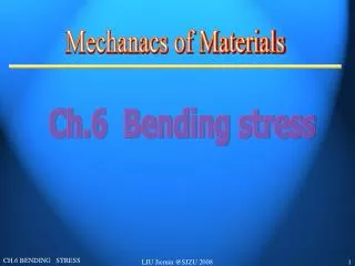
Analysis of Basic Load Cases Axial Stress Tension and Compression Shear Stress Examples Bending Tension/Compression & Shear Torsion Shear stress. Axial Stress. F= Axial Force (Newtons, N) A = Cross-Sectional Area Perpendicular to “F” (mm 2 ) E = Young’s Modulus of Material, MPa

E N D
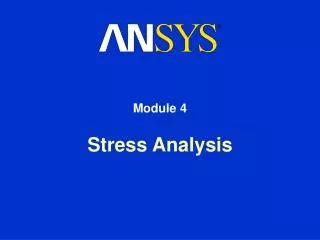
Analysis of Basic Load Cases • Axial Stress • Tension and Compression • Shear Stress • Examples • Bending • Tension/Compression & Shear • Torsion • Shear stress
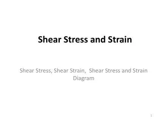
Axial Stress F= Axial Force (Newtons, N) A = Cross-Sectional Area Perpendicular to “F” (mm2) E = Young’s Modulus of Material, MPa L = Original Length of Component, mm s = Average Stress (N/mm2 orMPa) D=Total Deformation (mm) AE = “Axial Stiffness of Component”
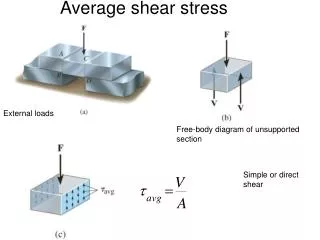
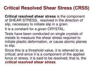
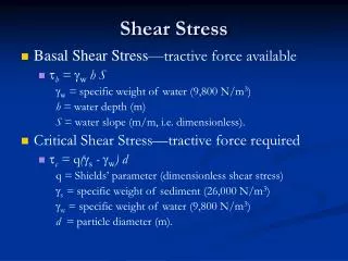
Direct Shear Stress taverage = Avearge Shear Stress (MPa) P = Shear Load A = Area of Material Resisting “P”
Examples of Direct Shear Stress D Bolted Joint with Two Shear Planes. P = 50 KN D = 13 mm tavg = ? Area of bolt (Ab) = p D2 / 4 = p (13)2 / 4 = 132.7 mm2 A resisting shear = 2 Ab tavg = P / 2Ab = 50000 N/ 2(132.7) mm2 = 188.4 MPa
Direct Shear II • 13 13 150 175 9.2 Fillet Weld Find the load P, such that the stress in the weld does not exceed the allowable stress limit of 80 MPa.
Solution: tavg = P / Aw = 80 MPa Aw = Throat x Total Length = (9.2)(175)(2) = 3217 mm2 P / 3217= 80 MPa P = (3217)(80) N = 257386 N = 257 kN
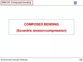
BENDING Before C After T Neutral Plane
Displacement in Beam y x v Curvature of Beam = M = Moment; EI = Bending stiffness of Beam
Bending Stress smax (C) y cc s ct smax (T)
Source of Internal Moment Fc d Ft Fc =Ft M=Ft d
Equivalent FBD M = Fd F d F
Bending Stiffness EI = Bending Stiffness E = Young’s Modulus (Material Dependant) I = Moment of Inertia (2nd Moment of Area) y Ixx = bh3 / 12 (mm4) h Iyy= hb3 / 12 (mm4) y b
Moment of Inertia Parallel Axis Theorem IXX = Ix’x’ + A y2 A If X-X is the neutral axis: SA y = 0
Try it! Locate the Neutral Axis and find the Moment of Inertia for the “T” section shown below. Consider the XXaxis, all dimensions are mm. 300 Ans:Ct= 200 mm Ixx = 2.50x108 mm4 50 X X 250 Ct 60
Neutral Axis Ok... 300 50 X X Ct/2 250 Ct 60
300 Ok... 50 75 X X 75 250 200 60 Mech 422 – Stress and Strain Analysis
Determine the Bending Stiffness of beams with this cross section made of: 1) Steel, E=203 000 MPa 2) Aluminum Alloy, E= 72 000 MPa 3) Glass Reinforced Polyester, E = 30 000 MPa
Determine the Bending Stiffness of beams • with this cross section made of: • 1) Steel, E=203 000 MPa • 2) Aluminum Alloy, E= 72 000 MPa • 3) Glass Reinforced Polyester, E = 30 000 MPa • Ans: • 1) EI = 5.08 x 10¹³ Nmm2 • 2) EI = 1.80 x 10¹³ Nmm2 • 3) EI = 0.75 x 10¹³ Nmm2 • In the ratio 1 : 0.36 : 0.15
Bending Stress: 300 kN 100 KN 200 KN M max = 200 KN.m s tension = 200x106 N.mm (200) mm / 2.50 x108 mm4 = 160 MPa MAX s compression = 200x106 N.mm (100) mm / 2.50 x108 mm4 = 80 MPa
Bending Shear A V
Bending Shear A V V S Fy = 0
Bending Shear V A V V V S Fy = 0 S Fx = 0 S M = 0
tavg = V / A tmax = 1.5 V / A A = b h Shear Stress - Bending For a Rectangle: tmax y b h tavg Max Shear Stress is at N.A.
Shear in Bending In General: b @ top of web ty = V Q / I b X X Q = 1st Moment of Area b @ N.A. b = width of the X-section at the plane of interest.
1st Moment of Area w • Consider all of the • X -section above (or below) • the plane of interest. z d y NA A=zw Qy = A d
Find The 1st Moment of Area at the Neutral Axis. (dimensions are mm.) 300 50 X X 250 Ct 60
The 1st Moment of Area at the Neutral Axis: (dimensions are mm.) Q = SAy 300 = (300)(50)(75) + (60)(50)(25) = 1.2 x 106 mm3 Note: At the N.A. b=60 mm 50 75 X X 25 200 250 60
Shear Stress: 300 kN 100 kN 200kN ty = V Q / I b V max= 2000 KN tmax= (200x103 N) (1.2x106 mm3) (2.50x108 mm4 (60) mm tavg = V/Aweb =(200x103 N) / (60)(300) mm2 = 11.1 MPa = 16 MPa
The “Maximum” Stress Distributions in the beam are: Shear Bending 300 Compression 80 MPa tmax=16 MPa 50 N.A. X X 250 60 160 MPa Tension
Torsion r T = Torque, G = Shear Modulus of Elasticity L = Length of Shaft, J = Polar Moment of Inertia q is in Radians!
tmax r D Shear Stress Distribution
Do Di Polar Moment of Inertia
Shear Modulus, G E = Young’s Modulus v = Poisson’sRatio Example: Steel E = 203 000 MPa, v = 0.3 G = 78 000 MPa
Shear Stress-Strain Curve Shear Stress, t Shear Modulus, G Shear Strain, g
500 mm Torque 150 mm 50 mm 25 KN
T = 25x103 N (150 mm) = 3.75x10⁶ N.mm L = 500 mm = p (50)4 / 32 = 6.14x105 mm4 3.75x10⁶ N.mm(500) mm = 3.9x10-2 = 2.2o = 6.14x105 mm4 (78000 N/mm2) 3.75x10⁶ N.mm (25 mm) = = 152.7 MPa 6.14x105 mm4 FS = 200/152.7 = 1.31
Superposition Assume the beam in our example is made of steel with a yield stress of 350 MPa. If it is subjected to an additional Axial Tension of 5000 kN along it N.A., will it yield ? 300 kN F = 5000 KN 200 kN 100 kN
Result: Axial Bending Net Compression F/A = 167 MPa 83 MPa (Tension) 80 MPa Tension + = N.A. Tension < 350 MPa No Yield! 160 MPa 327 MPa Tension
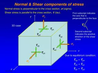
Rule for Adding Stresses: Like stresses at a point acting in the same direction and on the same plane can be added algebraically. • You can’t add a shear stress to a tensile/compressive stress. • You can’t add a stress in one location to one at another. • The effects of combined shear and tension/compression are covered later in this course.