Download
1 / 30
300 likes | 495 Views
TMB Mezzanine Upgrade. Indara Suarez Jason Gilmore Vadim Khotilovich Alexei Safonov. CMS Week EMU Meeting Cern Dec 11, 2012. TMB Upgrade Efforts: Outline. Motivation for changes to the TMB Mezzanine electronics design & testing This has been largely completed

E N D
TMB Mezzanine Upgrade Indara Suarez Jason Gilmore Vadim Khotilovich Alexei Safonov CMS Week EMU Meeting Cern Dec 11, 2012
TMB Upgrade Efforts: Outline • Motivation for changes to the TMB • Mezzanine electronics design & testing • This has been largely completed • Some small changes for final production • Performance and endurance considerations • Cooling and SEU mitigation • Firmware development • Fiber interface logic for DCFEB comparator data • Modify logic for monitoring/tuning trigger timing • Software development • Trigger timing/tuning tools to handle DMB-DCFEB control path • Production test control software development • Integration with other boards in the system • Production & Testing
CSC: Frontend Trigger Problem • Out-of-time PU induces deadtime at higher luminosity look at PU100 • Particular issue is the ME1/1 “TMB” building chamber track segments • Two aspects making ME1/1 special: • Very high occupancies • ME1/1 TMBs effectively serve two chambers (inner ME1/a, outer ME1/b) • Need better FPGA to maintain efficiency • The algorithm is ready (V. Khotilovich) • Design of prototype TMB completed • Improve muon trigger efficiency for |h|>2.1 • Rate increase compensated by requiring 3 station coincidence for |h|>2.1 • With new TMB can do w/o efficiency loss • Needs firmware modifications in CSCTF
TMB Design Considerations • Virtex 6 FPGA enhances our capabilities • Space & speed for improved trigger logic • Use 7 multi-gigabit serial links for data from DCFEBs • But it is a complicated chip to use • Requires 6 voltage levels, ~6 amps total • Power supply and cooling must be considered • Virtex 6 I/O is limited to 2.5V • Current TMB uses 3.3V signals throughout • Require external signal-level translators for the FPGA • We need the new board to be backwards compatible • Keep the copper connections for old CFEBs • Make fiber inputs available for new DCFEBs
Mezzanine Board Design • 2010 Mezzanine boards built & tested • Had some shortcomings, but no show stoppers • Test bed for firmware development & rad tests • Potentially vulnerable parts in this design • SNAP 12 optocouplers, Xilinx Virtex 6 FPGA & Prom, TI signal-level translator chips • All survived beyond 30 krad TID • 2012 Mezzanine very similar, with improvements • Fixed problems with XCF128 Prom & QPLL locking • Replaced rad-vulnerable regulators • These boards have extra components • Used for special tests, not needed for final design • They can be removed for final production
TMB Mezzanine 2012 Prototype Virtex 6 FPGA + PROM QPLL Snap 12 Fiber Transmitter socket (not used in final design) Snap 12 Fiber Receiver - fibers from 7 DCFEBs Signal-level translators 3.3 V to 2.5 V Dimensions: 7.5” wide by 5.9” high 11.1 mm clearance from TMB main board
Changes for Final Mez in 2013 Remove Parts Not needed… Might keep this -Convenient for fiber self-tests Can shrink PCB size to 7.5” wide by 5.25” high
TMB Mez: Preproduction • Mez preproduction PCB sent out for fabrication • 4 boards planned for completion next week • Parts are on order • Long-lead-time parts (FPGAs & Snap12s) already in hand • Parts assembly to follow • Finished board delivery to TAMU about Dec 20 • Changes in this revision • Removed all “test” components • Connectors & switches, Finisar transceiver, old Xilinx PROMs • The JTAG and CCLK lines are now much cleaner • Removed two redundant voltage regulators • Narrowed the board by 0.6” • Improves clearance situation with TMB main board • FPGA with more logic (240T), but same package (1156) • This may be needed for future trigger logic expansion plans • Transparent change in the LHC clock driving the QPLL
TMB Mez: PCB Layout Virtex-6 FPGA + PROM QPLL Snap12 Fiber Transmitter - only for testing Snap12 Fiber Receiver - fibers from 7 CFEBs PCB Dimensions: 7.5” wide by 5.25” high 11 mm clearance from TMB main board I/O Voltage-level shifters, 3.3 V to 2.5 V 10
TMB Mez: PCB Edge View • Close-up on the changed side of the board
Voltage Regulator Radiation Tests • Testing performed at the Texas A&M Nuclear Science Center • 1 megawatt reactor operating at 6 kW, provides 9.9 *108 n/cm2s • Multiple samples of several COTS regulators, two exposures • First exposure represents ~10 SLHC year dose • Second exposure adds ~20 SLHC years, total of 30 year dose • Regulator performance tested before and after each exposure • Regulators were unpowered during exposure • Several regulators showed no ill-effects • National Semi LP38501 and LP38853 • Micrel 49500 and 69502 • TI TPS74901 • Others did not fare so well… • Maxim 8557 • Sharp PQ035ZN1, PQ05VY053, PQ070XZ • TI TPS75601, TPS75901 • No improvement seen with additional cool-down time
SEU Studies for New CSC Boards • Tests were designed to study SEU effects in Virtex-6 and investigate mitigation methods for CMS Endcap • FPGA sensitive elements include GTX primitives, Block RAMs, CLBs • Use of these elements may vary for different boards & firmware • Measure SEU cross sections for each type to allow for rescaling • Expected 20 MeV neutron fluence in ME1/1 at HL-LHC: 2.7 *1011 n/cm2over 10-years • Initial radiation testing done in 2011 • Tests with 55 MeV protons • Performed at Texas A&M Cyclotron • Raw SEU sensitivity with *no mitigation* • Some FPGA elements are SEU sensitive • Many Block RAM errors, all single bit flips • CLB errors are common, but GTX errors are rare • Additional tests completed this summer at UC Davis • 64 MeV protons with higher flux • Tests in Block RAMs and CLBs *with mitigation* • We can effectively deal with SEUs in the FPGA
Impact of the 2011 SEU Measurements • How would these cross sections affect CSC operations in HL-LHC? • Snap12 Transmitter: < 1 SEU per year per link • Snap12 Receiver: ~1 SEU per week per link • These typically just affect a single data word • Finisar Optical Transceiver: ~7 SEU/day/link • Typically just affects a single data word • Low rate, less than one error in 3 *1013 bits • FPGA GTX Transceivers: ~3 SEU/year/link • FPGA Block RAMs: ~9 SEU/day/chip • These typically affect a single bit in a single cell • Need to investigate mitigation for FPGA BRAMs • FPGA CLBs: ~5.5 SEU/day/chip • Need to investigate mitigation for FPGA CLBs
Recent 2012 Radiation Studies • Testing at UC Davis Cyclotron • 64 MeV proton beam, flux up to ~1 *109 cm-2s-1 • Many of the same parts from previous SEU tests were retested using the same circuit boards • Snap12 parts are the only exceptions • New Emcore transmitters were tested in 2012 • All chips survived 30 kRad dose* • Monitored power for signs of latchup (none observed) • Some FPGA tests included mitigation this time • Enabled native ECC feature in Block RAMs • BRAM test used Read & Write under software control • Software designed to distinguish each failure mode • CLB tests based on triple-voting system • CLBs were implemented as a system of shift registers • Given common inputs and checked against each other • Error counts were recorded in registers and monitored by software
SEU Test Results 2012 (1) • Reflex Photonics 3.5 Gbps Snap12 Receiver: r12-c00501 • Random PRBG data patterns @3.2 Gbps on each of eight links • These SEUs only caused transient bit errors in the data • 2012 SEU cross section result: s = (6.4 ± 0.2) *10-9 cm2 • Similar to 2011 result, about 40% smaller: < 1 SEU per week per link • Combined 2011+2012: s = 9.5 *10-10 cm2 per link • Emcore 3.3 Gbps Snap12 Receiver: EMRS1216 • Same PRBG test as above • 2012 SEU cross section result: s = (9.8 ± 0.2) *10-9 cm2 • This gives s = 12 *10-10 cm2 per link • Similar to Reflex Photonics result, about 30% larger: ~1 SEU per week per link • Emcore 3.3 Gbps Snap12 Transmitter: EMTS1216 • Same PRBG test as above; tested two of these parts • These SEUs only caused transient bit errors in the data • 2012 SEU cross section: s = (1.7 ± 0.2) *10-10 cm2 • This gives s = 2.1 *10-11 cm2 per link • Nearly double the 2011 result for Reflex Photonics transmitter • Still very low rate of SEUs, so not a concern: ~1 SEU per year per link
SEU Test Results 2012 (2) • Finisar Optical Transceiver ftlf8524e2gnl: Transmit side • Gigabit Ethernet packet transmission tests to PCI card, 4 kB @ 500 Hz • Bad or missing packets received at the PC are “transmit” SEUs • These SEUs caused lost GbE packets and rare “powerdown” events • 2012 SEU cross section result: s = (4.3 ± 0.3) *10-10 cm2 • About 6 times the 2011 result; consistent with *6 increase in link duty cycle • Correcting for real CSC transmitter duty cycle: s = 6.7 *10-8 cm2 per link • We expect to see ~10 SEU per link per day during HL-LHC running • This is a low rate of single bit errors: just 1 error per 20 trillion bits on each link • Finisar Optical Transceiver ftlf8524e2gnl: Receive side • New test in 2012, load the BRAMs with data and read them back • Errors read back twice the same way are “receive” SEUs • These SEUs only caused transient bit errors • 2012 SEU cross section: s = (7.5 ± 0.1) *10-9 cm2 per link • We expect to see ~1 SEUs per link per day • *Three Finisars tested: one died at 33 krad, another at 41 krad • The third chip survived with 30 krad • TI Bus-Exchange Level-Shifter: sn74cb3t16212 • Still no SEU observed,2011+2012 result: s90% < 4.0 *10-12 cm2
2012 SEU Test Results • GTX Transceiver (55% are used in the FPGA) • Random PRBS data patterns @3.2 Gbps on each of eight links • These SEUs only caused transient bit errors in the data • 2012 GTX SEU cross section result: s = (10 ± 0.8) *10-10 cm2 • Similar to 2011 result, ~30% larger, consistent with additional active links • HL-LHC: still expect ~3 SEU/year/link • Block RAM (74% are used) • Use built-in Xilinx ECC feature to protect data integrity • Software controlled the writes and reads for BRAM memory tests • No errors were detected in the BRAM contents: mitigation at work • 2012 BRAM SEU cross section result: s90% < 8.2 *10-10 cm2 • CLB (43% are used) • Most of the logic is a shift register system with voting • Some of it was unvoted logic for control and monitoring • This reduced the “mitigation” effect of the voting • 2012 CLB SEU cross section result: s = (6.0 ± 0.5) *10-9 cm2 • Much smaller than 2011 SEU result, factor of 6 better: mitigation at work • With this we expect ~1 CLB SEU per FPGA per day at HL-LHC
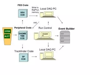
TAMU Production Test Stand • Standard P. Crate • TMB w/Mezz 2012 • Snap12 fiber linked to transmitter board on the bench • Custom loopback boards for DMB and ALCT/RPC tests • Special firmware • Tests controlled via VME and CCB w/customized test suite • Big software effort
Mezzanine Production & Testing • Equipment and procedures for production testing • TMB Mezzanine test stand with full capability at TAMU • CFEB emulator board with support for 5 cables • Fiber link tester for Snap12 link inputs • Will use a prototype board to transmit PRBS data to production boards • Crate tests with loopback boards (CCB, DMB, ALCT and RPC path tests) • VME and MPC tests performed with standard EmuLib tools • Software and automation • Developing a custom GUI to control tests and log all results • Vadim and students are doing this work • Final Mezzanine production begins early-2013 • Need 72 boards for ME1/1 operation • Fabrication & assembly should be completed ~April • Expect to test 10 boards per week at TAMU
TMB Mezz Installation in UXC • Installation in Peripheral Crates is (relatively) quick & easy • No crane, scaffolding or cherry picker required • Replace old TMB mezzanines with the new one • Plugs into socket on TMB • Must replace TMB front panels (two screws) • New panel will allow for DCFEB fiber connector • TBD, exactly where to place it on TMB front panel • Three options… I do have a favorite • Could be installed one crate at a time, easily ~3 per day • Then plug in fibers and update the TMB firmware
TMB Front Panel Modification • A fiber adapter must be added to the TMB front panel, but where? • Nearly enough space here, ~2mm more
TMB Front Panel Plan • We can change the 2-row right-angle LED header to a single row header, and use 3mm LEDs instead of 5mm • Seems trivial, but the manual wiring is fairly intricate… • We can keep all TMB connectors and the 8 LEDs • Just the LED labels have to move
Conclusion • TMB Mezzanine development coming to a close • We have the final design and a production plan for new TMB mezzanine boards • We have found satisfactory COTS parts to meet all our design requirements • Prototypes have been built & tested Good results from radiation & performance tests • Development work still needed in SEU mitigation firmware • Preproduction run is in progress • We need 4 more boards for various worldwide test sites next year • Final CSC ME1/1 Electronics production begins soon • Need 72 each for new TMB, plus some spares • Start producing these early in 2013 • Installation in CMS starting summer 2013
SEU Testing of COTS Components (1) • Testing performed at Texas A&M Cyclotron • 55 MeV protons with uniform flux, collimated to 1.5” diam • Maximum proton flux ~3 *107 cm-2s-1 • 45 to 90 minute runs on each target device, 5-10 kRad • Two samples tested for each COTS component • Reflex Photonics Snap12 Receiver: r12-c01001 • PRBG data transfers @3.2 gbps on each of six links • s = (8.18 ± 0.34) *10-9 cm2 • Also tested to ~30 krad TID at TAMU reactor: no problems • Reflex Photonics Snap12 Transmitter: t12-c01001 • Tested for use in DMB upgrade • PRBG data transfers @3.2 gbps on six links • s = (7.31 ± 2.44) *10-11 cm2 • Finisar Optical Transceiver: ftlf8524e2gnl • Tested for use in CFEB upgrade • randomized GbE data packets to PC • s = (1.02 ± 0.27) *10-10 cm2
SEU Testing of COTS Components (2) • Xilinx Virtex-6 FPGA: xc6vlx195t-2ffg1156ces • GTX Transceiver (55% used) • PRBG data transfers @3.2 gbps • s = (7.55 ± .79) *10-10 cm2 • Block RAM (74% used) • 4 kB BRAM readout to PC • s = (5.69 ± .58) *10-8 cm2 • CLB (38% used): • 4 kB CLB-RAM readout to PC • s = (3.71 ± .47) *10-8 cm2 • TI Bus-Exchange Level-Shifter: sn74cb3t16212 • PRBG data transfers @15 MHz • No SEU observed, s90% < 1.73 *10-11 cm2 • Additional testing performed recently • UC Davis, 64 MeV proton beam • Using higher-rate beam, all chips survived 30 kRad dose