Download
1 / 22
240 likes | 409 Views
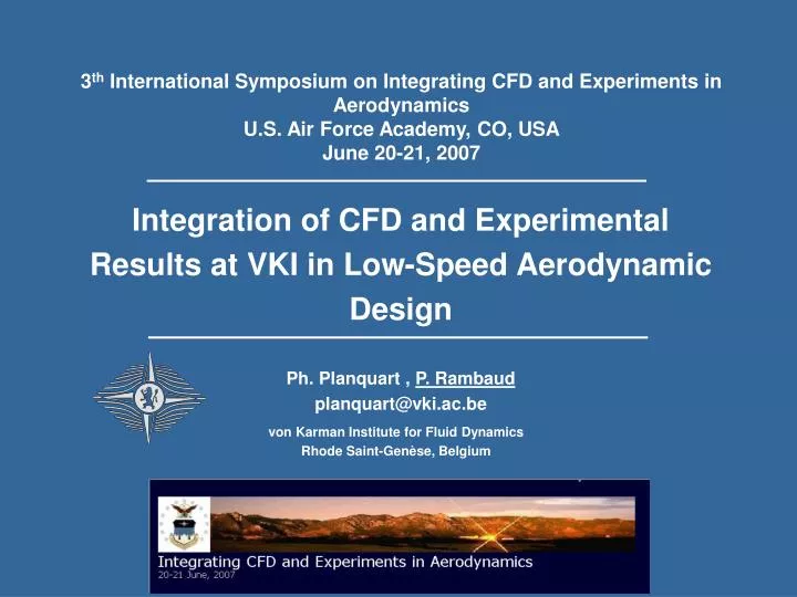
3 th International Symposium on Integrating CFD and Experiments in Aerodynamics U.S. Air Force Academy, CO, USA June 20-21, 2007. Integration of CFD and Experimental Results at VKI in Low-Speed Aerodynamic Design Ph. Planquart , P. Rambaud planquart@vki.ac.be.

E N D
3th International Symposium on Integrating CFD and Experiments in AerodynamicsU.S. Air Force Academy, CO, USAJune 20-21, 2007 Integration of CFD and Experimental Results at VKI in Low-Speed Aerodynamic Design Ph. Planquart , P. Rambaud planquart@vki.ac.be von Karman Institute for Fluid Dynamics Rhode Saint-Genèse, Belgium
Outline • Introduction • Description of the test facilities and CFD code • Example I: Flow- structure interaction problem • Example II: Aerodynamic design of a new polar station • Example III: Aerodynamic design of an ultra-streamlined land vehicle • Conclusions
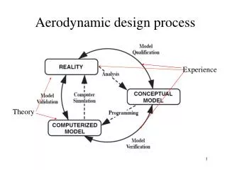
Introduction • Integration of CFD and Experiments is required when each method alone is not enough to reach the final objective (with correct reliability, delay or accuracy). • The advantage of each method is then combined in an integrated project. • The best integration is obtained when Experimental and Numerical engineers are interacting each others. • Illustration through three examples: • Example I: Improvement of sun protection system under wind load. • Example II: Aerodynamic design of the new Belgium Antarctica polar station. • Example III: Aerodynamic design of an ultra-streamlined land vehicle. • For each project, the requirements and the methodology are different but the final goal was to obtain an optimized aerodynamic design.
Collector Description of the test facilities and CFD code • Experimental tests are performed in the VKI Low Speed Wind Tunnel L1. L1-A wind tunnel with a free jet test section L1-B wind tunnel – wind engineering facility • Test of the Belgian polar station • Test on the ultra-streamlined land vehicle • Flow-structure interaction • The CFD investigation is performed using FLUENT from the ANSYS with RANS or URANS approaches.
1/7 Flow structure interaction • Sun protection system to be placed alongside building. • Vibrations were observed during heavy storms. • Goal: Modify the blade shape to eliminate/diminish the fluid-structure interaction.
2/7 L Flow structure interaction • The investigation has started with wind tunnel tests. • High speed image recording has provided the deformation mode of the different blades. • Snapshot of a test shows that the vibrations of the blades are more related to torsion than bending. Sun protection system in VKI - L1-A wind tunnel
3/7 L Flow structure interaction • Mechanical investigations using a Computer-Aided Engineering (CAE) package (Solidworks) has provided the natural frequencies of the blades, and the deformation modes. Effect of the length of the blades on the vibration frequency Bending Torsion Bending
4/7 H [-] H Contours of velocity magnitude at t=1.13 s. Contours of velocity magnitude at t=1.125 s. Flow structure interaction • Vortex shedding frequencies have been obtained using a CFD approach. • URANS simulation of the flow field around a single blade for the same wind direction as in the wind tunnel is performed. • For a wind velocity of 10 m/s, the vortex shedding frequency found numerically is equal to 33 Hz. • This resulthas been validated by the wind tunnel tests, for which vibrations related to torsion were observed to begin at a wind tunnel velocity of 10 m/s.
5/7 Old design Flow structure interaction • Ten different geometries have been proposed and analyzed (CAE). New designs
6/7 New designs Old design Flow structure interaction • Natural frequencies of the ten new blades were close to each other. • The best shape had to be found based on CFD (flow field around the blade). • The final blade presents reduced velocity acceleration leading to lower pressure fluctuations and lower amplitude of vortex shedding. • The final blade was built and then tested in the wind tunnel. • Very good results, meaning no fluid-structure interactions, have been observed at low speed with the proposed blade geometry.
7/7 Flow structure interaction
1/5 Aerodynamic design of a new polar station • Aerodynamic design of the new Belgian Polar station for the Antarctica. • The presence of the most intense winds on Earth, so called the katabatic wind leading to wind speed in excess of 65 m/s. • Transport of large quantities of snow that can bury the building very quickly. Most important aspects have to be considered: • Snowdrift • Wind loading.
2/5 Aerodynamic design of a new polar station • The aerodynamic design is divided in two parts: • A conceptual phase • A detailed analysis phase • In the conceptual phase, the ability of different buildings to cope with intense drifting snow has been tested. • This investigationcouldonly be made with wind tunnel tests. • The methodology developed by VKI has allowed to find experimentally regions of snow accumulation and snow erosion.
3/5 Aerodynamic design of a new polar station • In the detailed analysisphase, the height and position of the building on the ridge has been defined. • Aerodynamic wind loading on the building has been evaluated using CFD for different positions of the building. • CFD results were also used to understand the flow pattern around the building. The vortices behind the building are responsible of the snow erosion and snow accumulation. • Wind tunnel results have been revisited using CFD “flow visualization”. Numerical simulation showing the vortices behind the building Flow visualization using CFD
4/5 Aerodynamic design of a new polar station • Final building configuration was built and tested in the wind tunnel. • Local pressure measured in the wind tunnel have been compared to CFD results. • Local CFD data are used for the mechanical design of the external panels. CFD results showing the pressure distribution on the different parts Final model – instrumented with pressure tabs
5/5 Aerodynamic design of a new polar station
1/5 Aerodynamic design of an ultra-streamlined land vehicle • The World Solar Challenge is organized every two years and is a 3000 km long race for cars powered by sunlight (www.wsc.org.au/2007/). • New rules for the 2007 Challenge are affecting the external aerodynamic shape of the solar car. • Two phases for the design • Definition of the concept • Detailed analysis of the aerodynamic shape • Design started by using CAD package. CAD geometries were then inserted in the CFD package to get aerodynamic data. • First phase: • Exact value of the drag was not the major concern • Quick information to define the shape of the car. • Final car concept includes two front wheels and a back wheel below the driver that will be used to power the car.
2/5 About 5.5 millions cells Aerodynamic design of an ultra-streamlined land vehicle • Second phase: detailed investigation of the flow field around the car (CFD). • Parameters that were tested: • Thickness and shape of the main plate supporting the solar cells • Shape of the canopy • Thickness of the wheel system • Position of the canopy on the car • Scatter is obtained in the drag area coefficient depending on turbulence models!!
3/5 Aerodynamic design of an ultra-streamlined land vehicle • The following questions were remaining at the end of the CFD analysis: • What is the exact value of Cd.A ? • How to improve the geometry of the canopy to reduce the overall drag? • What is the best geometry for the wheel protection system ? • What is the influence of side-wind on the drag and side force ? • What would be the influence of dust or dirt on the surface of the solar cells on the aerodynamic drag ? • What would be the sensitivity to a small change of the angle of attack of the car on the lift, the pitching moment and the drag? • Wind tunnel tests had to be performed because it was the quickest wayto answers to these questions.
4/5 Aerodynamic design of an ultra-streamlined land vehicle • Wind tunnel tests were performed on a model at scale 1/3. • All the tests have been performed in one week. • Drag area coefficient (Cd.A) was lower than the one predicted by CFD (reduction by more than 10%). Oil visualization showing the detachment position on the canopy Ultra-streamlined land vehicle in wind tunnel on six-component floor balance • Final validation will be the race in October 2007.
5/5 Aerodynamic design of an ultra-streamlined land vehicle
Conclusions • Integration of CFD and Experiments can lead to a better aerodynamic design. • Communicationbetween wind tunnel specialists and CFD specialists is crucial throughout the studies. • The three examples have also shown that a single approach is often not enough to obtain the optimized design.