Download
1 / 21
210 likes | 334 Views
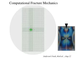
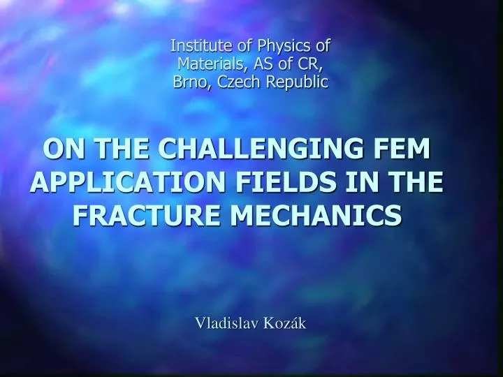
ON THE CHALLENGING FEM APPLICATION FIELDS IN THE FRACTURE MECHANICS. Institute of Physics of Materials, AS of CR, Brno, Czech Republic. Vladislav Kozák. Outline. 1. Introduction 2. Local approach -Beremin 3. GTN model 4. Cohesive-zone modelling 5. Summary. 1.Introduction FTTD.

E N D
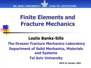
ON THE CHALLENGING FEM APPLICATION FIELDS IN THE FRACTURE MECHANICS Institute of Physics of Materials, AS of CR, Brno, Czech Republic Vladislav Kozák
Outline • 1. Introduction • 2. Local approach -Beremin • 3. GTN model • 4. Cohesive-zone modelling • 5. Summary
1.Introduction FTTD lower transition upper stress control fracture SSY deformation control fracture lower bound upper bound transition
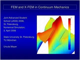
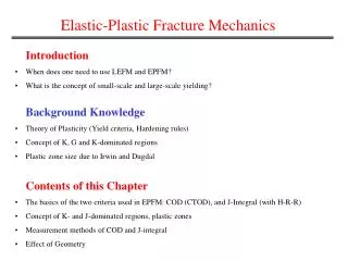
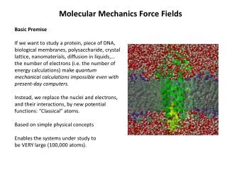
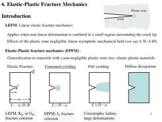
Three different approaches to the damage modelling • no damage evaluation, elasto-plastic constitutive equation, process zone is small, K, J, C* • separation of surfaces is admitted, material outside is described conventionally, the process zone is some surface region, fracture criterion is cohesive law • softening behaviour is introduced into the constitutive model, e.g. accumulation of damage, described by additional internal variables, GTN
Plastic zone ahead the crack tip region: condition SSY large deformation J-integral conception K faktor conception non defined only by one parameter condition elasto-plastic conditionLSY
2. Local approach - Beremin • · Beremin model • 1. averaging stresses over FPZ • 2. probability of fracture • · Extension to Fracture Mechanics • 1. direct toughness prediction for SSY • 2. TSM, Minami, Koppenhoefer, Ruggieri
f0 fC GT plast. HMH plasticity D 3. Gurson-Tvergaard model(GT) nucleation fN = 0,004 eN = 0,3 SN = 0,1 f0 = 0,005 fC = 0,035 q1 = 1,5; q2 = 1 D = 0,2 mm
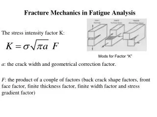
f * fu* fc GT GTN fF fc f GT x GTN model q1, q2, q3 are used to adjust the model sm is hydrostatic stress sYS is yield stress f* is void fraction, fc is the critical void fraction for coalescence fF is the final value of f, fu*=1/q1. dfnucl.=Adep
f1=0.0073 f2=0.0073 f3=0.0083 f4=0.0126 f5=0.0131 f6=0.0349 500 mm material parameters identification void distribution in non-affected area void distribution in the neck area of the round tensile bar
the influence of the mesh size on the curve elongation-contraction
varying values of f0 and fN and determination of input data f0 = 0.005, fF (fC) = 0.035 q1 = 1.5, q2 = 1 (q3 = q12) eN = 0.3, SN = 0.1 fN = 0.004
W a L/2 B/2 3PB SE(B) L = 250 mm l = 200 mm W = 50 mm B = 25 mm a = 25,25 mm
D/2 2.5 mm mesh size
J J0.2BL J0.2 JI SZW JI 0.2 mm Da DaSZW FEM J=1,39syDa
The influence of q2on the values of J-integrálu at stable crack initiation The influence of the h parameter (triaxiality parameter)
5. Summary • The coincidence of the results of the numerical modelling and the experiment is generally the basic criterion.