Download
1 / 14
140 likes | 259 Views
Random Walk through Trigger Calibration and Monitoring. Norman Gee. 8-10 nov 2006. Topics…. Digital Timing (crucial; not mentioned again) Pulser Calibration Database Beam: retiming, real pulses, energy loss Monitoring (first ideas). Raw Signal.

E N D
Random Walk through Trigger Calibration and Monitoring Norman Gee 8-10 nov 2006
Topics… • Digital Timing (crucial; not mentioned again) • Pulser Calibration • Database • Beam: retiming, real pulses, energy loss • Monitoring (first ideas) N. Gee Calibration Overview
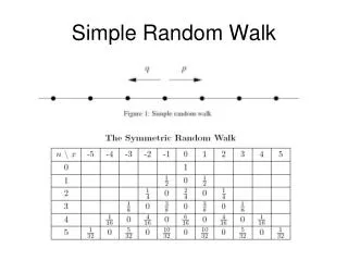
Raw Signal N. Gee Calibration Overview
Analogue Pulse Shape and Timing – using calibration pulser • FADC DAC scan and Pedestal Run • Find the DAC value needed to set the chosen pedestal • Measure exact FADC pedestal and noise. DAC scan only sets pedestal to 3-4 FADC counts • Coarse Timing Scan • Measure DAQ readout memory offset • Fine Timing Scan • Measure fine timing. May change coarse timing setting • Analogue Pulse Shape • Measure analogue pulse shapes • Status: All of these now store results in database and are ~automatic N. Gee Calibration Overview
Fine Timing N. Gee Calibration Overview
FIR Filter and “Electronics ET Calibration” • FIR Filter coefficients • Compute the coefficients and “drop bits” settings for each trigger tower. • Electronics ET Calibration • Compute receiver and LUT values to reproduce simulated ET deposits • All these results to go to database in a “Pulser” settings area N. Gee Calibration Overview
Database handling N. Gee Calibration Overview
Detector Performance and Beam Corrections • Physics Pulse Timing – Strategy for measurement • Obtain physics timing from crenellated beam structure. • Physics Pulse Shape • Particle pulses not identical in shape to charge injection systems. • Measure particle pulse shapes – not so easy as amplitudes are small and varying, and can have pulses in adjacent timing bins. • Then convert to FIR coefficients. Initially adjust ET calibration to keep same area under pulse per GeV? • Eventually recalibrate with physics channels. Needs lots of data • This gives Deposited energy. • Correction factors to get to Object energies: • Initial values have to come from MonteCarlo. Eventually tune with beam • dead material. One (multiplicative?) factor per tower • dead cells. One factor per tower, probably just eta and layer dependent N. Gee Calibration Overview
Analogue Checks • These can all be done with the same L1Calo run mechanisms, but need different calorimeter conditions and/or different data analysis • Connectivity – verify the routing of calorimeter towers to PPMs • Crosstalk – check no significant communication between towers. • Relative timing of raw cells – check that they are equal for a tower • Pulse shapes from raw cells – check they are very similar • Pulse amplitudes from raw cells – check injected energies contribute equally • Match precision readout to tower readout – confirms physics calibration N. Gee Calibration Overview
Tuning… • Poor resolution in detector overlap regions and at low/high . • Raise thresholds locally if rate explodes. • Jet-ET estimation • Only an approximation derived from number of jets passing different thresholds – if a jet passes thr1 but not thr2, its Jet-ET might be (thr1+thr2)/2 • Can tune exactly where the jet-ET sits here. N. Gee Calibration Overview
Monitoring • DCS – Voltages and temperatures and currents • measured on every module in every crate. Not further discussed. • Non-Event-Related • Error counters on all modules – vital but boringly zero. • Beam-monitoring • Event-related • Parasitic readout of individual modules (checks of digital algorithms) • access to event info as it is transformed from calo pulses to the L1A • Comparison with precision calorimeter readout • Check trigger digitisation & Bunch-crossing Identification against full calo readout • Calibration N. Gee Calibration Overview
Beam Monitoring – Histograms and Rate Metering • Can choose histogram or rate meter per channel. Both happen BEFORE L1A. • Input datum choice: raw FADC signal or calibrated ET • Histogramming function • One bin per LHC bunch number. Incremented whenever input value exceeds threshold, and is within lower and upper bunch number. Stops when one channel overflows. • Rate meter function • Counts how often a threshold is exceeded – output is time (in BC intervals) and a count (one of each per tower) N. Gee Calibration Overview
Monitoring Areas – posse output • Correct behaviour: • Algorithm inputs match precision readout from calo cells • correct tower building and digitisation • Algorithm outputs are as expected from simulation • correct algorithms loaded, thresholds OK, hardware OK • Sensible Behaviour • eta/phi RoI and Energy distributions • eta/phi trigger hits, multiplicities • Threshold behaviour and rates for all triggers N. Gee Calibration Overview