Download
1 / 27
270 likes | 399 Views
Harmonics and PFC. The love story By Pol Nisenblat. THE FUTURE OF POWER QUALITY. DEFINITIONS. PROBLEMS. “DETUNED” SOLUTIONS. TUNED SOLUTIONS. HOW TO CHOOSE. OPEN DISCUSSION. ELECTRICAL POWER SOURCE.

E N D
Harmonics and PFC The love story By Pol Nisenblat
THE FUTURE OF POWER QUALITY DEFINITIONS PROBLEMS “DETUNED” SOLUTIONS TUNED SOLUTIONS HOW TO CHOOSE OPEN DISCUSSION
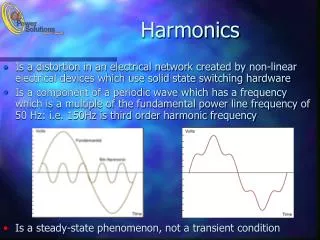
ELECTRICAL POWER SOURCE • It is worldwide common practice to assume that utilities generate a near perfect sine wave voltage • Typical electrical energy source is introduced by “voltage” source
DISTRIBUTION TRANSFORMER • Typical Internal Impedance is only 2-7% of the fully loaded Secondary
IDEAL ENERGY SOURCE • Simplified power control by periodical switching (chopping) • Nonlinear load operation generatescurrent waveform distortion
HARMONICS - DEFINITIONS • Harmonics are integral multiples of some fundamental frequency that, when added together, result in a distorted waveform + f(x) = sin(x) sin(5x) f(x) = 5 sin(5x) f(x) = sin(x) + = 5
HARMONICS - DEFINITIONS • Harmonic order are MULTIPLES of the fundamental frequency. • Typical Harmonics are the 3rd, 5th, and 7th • Where H3 = 150 Hz, H5 = 250 Hz, H7 = 300 Hz (at 50Hz world) • In fact, any waveform may be constructed from a sine wave and some number of its harmonics like:
HARMONICS – MOST IMPORTANT DEFINITIONS • Harmonics are originated at the load side! • Harmonics are created in the current! • Harmonic sources are - current sources
HARMONIC SOURCE • High internal impedance • The harmonic current is being PUSHED towards lowest external impedance path
HARMONIC CURRENT FLOW • Typical harmonic current flow is towards distribution transformer 0.01 Ohm 1 Ohm
HARMONICS – PROBLEMS? • I2r losses + “skin” effect • Voltage distortions • Iron-core losses • Cables/transformers overheat • Upstream pollutions • But, the real problems are yet to come
HARMONIC CURRENT WITH PFC • Where the H5 current should go now?
PARALLEL RESONANCE Parallel resonance =Infinity impedance
PARALLEL RESONANCE • High impedance at the resonance frequency • The resonance frequency changes with changed number of capacitor groups (N)
PARALLEL RESONANCE • Harmonic current turns back to the loads • Harmonic VOLTAGE raises dramatically • Harmonic current circulates (ping pong) between capacitors and distribution transformer V
PARALLEL RESONANCE – WHAT TO DO? • Xl1 reactor in series to the capacitor moving parallel resonance frequency downstream • The new resonance frequency at:Xc=Xl+Xl1 • Locate parallel resonance frequency below lowest dominant harmonic
kVAsc hr = kVAC PARALLEL RESONANCE FREQUENCY –”RULE OF THUMB” • Where hr is the harmonic number of the parallel resonance • Unfortunately, not accurate enough
HOW TO CALCULATE PARALLEL RESONANCE FREQUENCY? • For those who love formulas:
HOW TO CALCULATE PARALLEL RESONANCE FREQUENCY? • Unfortunately, Xl (Xtr) value which is actually the total distribution network inductance at the frequency of interest - is unknown • But, we do know that the parallel resonance frequency would always be locateddownstream to the serial resonance frequency between Xl1-Xc
WHAT FREQUENCIES ARE SAFE? • Even” harmonics are normally not present • “Triple” harmonics are canceled on DELTA connected loads with balanced 3rd harmonic • On balanced loads and 3 phase DELTA capacitors cases, tuning in H3.5-H4.2 ranges are most popular
DETUNED SOLUTION - DEFINITIONS • Tuned frequency is defined by serial resonance point • Serial connected reactors are defined by % rather then Henries • Reactor’s % defined as impedance at the fundamental frequency with respect to the capacitor’s impedance at the same frequency
TUNED SOLUTIONS - FILTERS • Passive filters are “tuned” to just below the harmonic frequency • Care should be taken – not to overload! Low impedance path at 5th harmonic
TOO HIGH HARMONIC LEVELS? • Disconnect ALL PFC capacitors and check again • Significant difference? – Use detuned solution • No difference? – Use tuned solution • 2nd and 4th harmonics too high? - Check voltage converters • Weak network? 14% detuned solutions are preferred • Balanced 3rd harmonic in current? – Use 5.67-7% solutions • Unbalanced compensation? – Use 14% solutions only • Voltage harmonics without current sources? • Don’t use filters! Speak to utility.
Questions? Contact: Asaf Laifer Alaifer@elspec-ltd.com 972-4-6174127