Download
1 / 68
710 likes | 919 Views
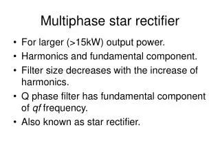
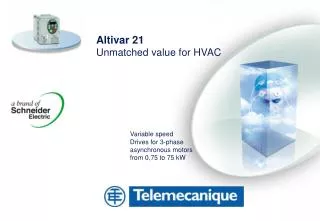
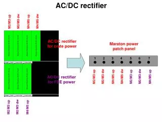
Intelligent Rectifier ALTIVAR 68R. 4 Quadrant. DC voltage source. Complete solution with : Line filter Inductance Guaranteed “0”Harmonics. What is it an Intelligent Rectifier ALTIVAR 68R ?. 1. Marketing advantage. Recuperative braking solution (energy feedback to mains).

E N D
4 Quadrant DC voltage source • Complete solution with : • Line filter • Inductance • Guaranteed “0”Harmonics What is it anIntelligent Rectifier ALTIVAR 68R ? 1. Marketing advantage
Recuperative braking solution (energy feedback to mains) Input IGBT bridge Sinusoidal current in all operating states Mains voltage failure during brake operation leads to a controlled switching off (parameter adjustable response) Emergency operation (parallel operation) with braking unit possible AdvantageIntelligent Rectifier ALTIVAR 68R
Intelligent rectifier B6- IGBT bridge InverterB6- IGBT bridge motor cos j =1 generator cos j =1 cos j compensation AddvantageIntelligent Rectifier ALTIVAR 68R
OFFER Intelligent Rectifier ALTIVAR 68R 98 Kw / 8.5 mF ATV 68-RC10N4 VW3A68R508 VW3A68R415 Option RFI filter VW3A68R466 Intelligent Rectifier Inductance Line Module Q1 NH NDS L11 L1 98kW/8.5mF L1 L1 L12 L2 L2 L2 L13 L3 L3 L3 K1 F4,F5,F6 F7 F8 F9 X32 LW6 V1 X32 X31 X31 K2 X30 X30
VW3A685.. VW3A684.. ATV 68-R Inductance Line Module Intelligent Rectifier Q1 NDS NH L1 L11 L1 L1 L2 L12 L2 L2 L13 L3 L3 L3 K1 F4,F5,F6 F7 F8 F9 X32 LW6 V1 X32 X31 X31 K2 X30 X30 OFFER Intelligent Rectifier ALTIVAR 68R
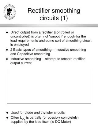
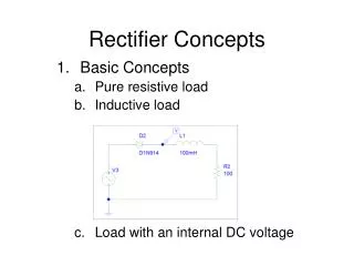
I Diode I IGBT IGBT are pulsing at 5 (4) kHz When the IGBT is on, the current flows through it When the IGBT is switched off, the choke forces the flow of current to continue however this time through the diode. The DC link will be overcharged during this time. A change in the pulse/interval ratio regarding the voltage phase position influences the energy direction and the cos j ATV 68-R – Basic principle P = U x I P = U x I x cosj
DC t t ATV 68-R – Start sequence 1. Start command on the Intelligent Rectifier ATV 68-R The DC capacitors are pre-charged via the pre-charging circuit All ATV 68 drives are still locked. (B3.06) U 2. After the pre-charging sequence the IGBTs start to work and overcharge the DC link. The IR internal voltage control is activated. Now all ATV 68 drives (linked to the DC bus) are ready to start
Marketing SegmentIntelligent Rectifier ALTIVAR 68R 2. Le marché du modul reversible Secteur Industrie (et infrastructures process) Utilités bâtiment (et infrastructures) de marché Grandes industries Industrie Résidentiel Tertiaire PMI-PME Processus Process Batch Manufactures de décision Machines Machines simples modulaires Constructeur 1A ATV28 .ATV11 2A ATV58 de 2A ATV58 Machines machines complexes Grands tableaux 4 /2B ATV68 Machines Utilisateur spéciales (ingénierie Locaux 1B ATV58 ATV68 ATV68R intégrateur) techniques 1B ATV58 ATV68 Contrôle séparé Installateur Tab. Logement Moyens tableaux
Marketing Segment Intelligent Rectifier ALTIVAR 68R Fonctions / Performances 2. Le marché du modul reversible • Positionnement dans l'offre VVD Très Hautes performances Communication Nombreuses fonctions complexes ATV58 CVF ATV68F ATV68R Fortes puissances Hautes performances Nombreuses fonctions complexes ATV58 Hautes performances Communication Fonctions complexes Bonnes performances Fonctions simples ATV68 ATV28 ATV11 Puissance en kW 0,75 75 630 0,18 160 15
Size 3 4 5 2 ATV68R C10N4 C17N4 C34N4 C67N4 Input Nominal power [kVA] 100 kVA 174 kVA 338 kVA 675 kVA Nominal input current In / Un : 400 VAC 144 A 251 A 488 A 975 A In / Un : 440 VAC 131 A 228 A 441 A 885 A In / Un : 470 VAC 122 A 213 A 414 A 826 A Maximal input current for 60 s in 10 min In / Un : 400 VAC 173 A 301 A 586 A 1170 A In / Un : 440 VAC 157 A 274 A 529 A 1062 A In / Un : 470 VAC 146 A 256 A 497 A 991 A OFFER Intelligent Rectifier ALTIVAR 68R
Size 2 3 4 5 ATV68R C10N4 C17N4 C34N4 C67N4 Output Nominal power POUT [kW] 98 kW 171 kW 332 kW 663 kW Permanent output current In / Un : 650 VDC 150 A 263 A 511 A 1021 A In / Un : 720 VDC 136 A 237 A 458 A 920 A In / Un : 790 VDC 123 A 216 A 419 A 836 A Ambient conditions Working temperature [°C] 0…40°C 0…40°C 0…40°C 0…40°C Efficiency [%] > 97 % > 97 % > 97 % > 97 % Sound pressure level < 60 dB(A) < 63 dB(A) < 67 dB(A) < 68 dB(A) Protection class IP00 IP00 IP00 IP00 OFFER Intelligent Rectifier ALTIVAR 68R
VW3A685.. VW3A684.. ATV 68-R Inductance Line Module Intelligent Rectifier Q1 NDS NH L1 L11 L1 L1 L2 L12 L2 L2 L13 L3 L3 L3 K1 F4,F5,F6 F7 F8 F9 X32 LW6 V1 X32 X31 X31 K2 X30 X30 OFFER Intelligent Rectifier ALTIVAR 68R
NH Q1 L1 L3 L2 OFFER Intelligent Rectifier ALTIVAR 68R 98 Kw / 8.5 mF ATV 68-RC10N4 Intelligent Rectifier VW3A68R466 Line Module Max 1.5m X32 X30 X31 X30 X31 X32 +- L1 L3 L2 98kW / 8.5mF L11 L13 L12 L1 L2 L3 PE + VW3A68R415 Option RFI filter VW3A68R508 Inductance PE Q1
X31 X30 X32 L11 L12 L13 X30 X32 X31 Max 1.5m PE NH Q1 L1 L3 L2 OFFER Intelligent Rectifier ALTIVAR 68R 171 Kw / 19 mF ATV68RC17N4 Intelligent Rectifier 171kW / 19mF VW3A68R467 Line Module x1 x3 x2 L3 L2 L1 L1 L2 L3 VW3A68R435 Option RFI filter VW3A68R509 PE Inductance
X31 X30 X32 NH Q1 L1 L3 L2 OFFER Intelligent Rectifier ALTIVAR 68R 332 Kw / 25.5 mF ATV68RC34N4 Intelligent Rectifier VW3A68R468 Line Module + + x1 L11 L12 x3 x2 L13 332kW / 25.5mF X30 X32 X31 X30 X32 X31 Max 1.5m L3 L1 L2 PE L1 L2 L3 PE VW3A68R465 Option RFI filter VW3A68R510 PE Inductance
PE NH Q1 L1 L3 L2 OFFER Intelligent Rectifier ALTIVAR 68R 663 Kw / 51 mF ATV68RC67N4 + Intelligent Rectifier - VW3A68R469 663kW / 51mF Line Module x20 x20 + + L12 - L13 - - x1 L11 Max 2.5m + + x3 x2 - x2 - - x2 X32 X31 x1 x1 X30 Max 2.5m X32 X31 X30 L1 L3 L2 PE PE PE L1 L2 L3 PE VW3A68R495 Option RFI filter 2x VW3A68R510 Inductance L1 L2 L3 L1 L3 L2
Length of the DC cable connection 68 – 68-R (for 4-Q combination): size 2 - size 4 max. 5 meter size 5 max. 10 meter The design of a DC connection for multimotor applications has to be done with DC bus bars systems ! max. extension: 50m long (on low- inductive versions) OFFER Intelligent Rectifier ALTIVAR 68R
Hoisting Textile Fan and pump 0 harmonics solution ApplicationIntelligent Rectifier ALTIVAR 68R A. Marketing / 1. Enjeux
ApplicationIntelligent Rectifier ALTIVAR 68R A. Marketing / 1. Enjeux Casting Crane 110/40t, Bridge 32m customer VOEST Alpine Austria Drives : Main Hoist : 2 x ATV68 C 23 N4 Auxilary Hoist : 1 x ATV68 C13 N4 Gantry : ATV68 C15 N4 Trolley : ATV68 C10 N4 2 x ATV68 RC34 N4
ApplicationIntelligent Rectifier ALTIVAR 68R A. Marketing / 1. Enjeux Tongs Crane 90t customerDillinger Hütte Germany Drives : Main Hoist : 2 x ATV68 C 63 N4 Auxilary Hoist : 2 x ATV68 C23 N4 Rotary : 2 x ATV68 C 10 N4 2 x ATV68RC67N4 Gantry : 2 x ATV68 C23 N4 Main Trolley : 2 x ATV68 C13 N4 Aux. Trolley : 2 x ATV68 C10 N4 2 x ATV68 RC34 N4
ApplicationIntelligent Rectifier ALTIVAR 68R A. Marketing / 1. Enjeux Magnet Crane 50/10t customer VOEST Alpine Austria Drives : Main Hoist : ATV68 C 23 N4 Auxilary Hoist : ATV68 C10 N4 Gantry : ATV68 C19 N4 ATV68 RC34 N4
ApplicationIntelligent Rectifier ALTIVAR 68R A. Marketing / 1. Enjeux Crane customer VOEST Alpine Austria Drives : Main Hoist : ATV68 C 23 N4 Auxilary Hoist : ATV68 C10 N4 Gantry : ATV68 C19 N4 ATV68 RC34 N4
Intelligent Rectifier ALTIVAR 68R B.Technical point4.Comparison of brake variants4.1 Motor brake4.2 DC – Brake4.3 Braking unit with braking resistor4.4 Inverter operation with a fully controlled B6 thyristor bridge4.5 Intelligent Rectifier Altivar 68-R
P mechanical Stator losses Cable losses IGBT switching loss IGBT current losses Capacitor losses Generator Motor Motor brake (see ATV 68 - C1) RectifierB6- rectifier bridge InverterB6- IGBT bridge Motor Motor cable Total losses: approx. 10% of P nominal (with 150% In, reactive current)
No additional components required No additional costs Available brake power approx. 10% of P nominalBraking torque increases with falling speed! No linear braking ramp Braking energy is dispersed throughout the whole system In brake operation no energy is required from the mains Typical use of „emergency stop“ Motor brake (see ATV 68 - C1)
P mechanical Rotor losses Stator losses P electrical Generator Motor DC- Brake RectifierB6- rectifier bridge InverterB6- IGBT bridge Motor Motor cable Risk of fault! DC- operating brake ≠ DC- holding brake
No additional components necessary No additional costs Available brake power approx. 10% of P nominalBraking torque increases with falling speed No linear braking ramp Mechanical braking energy is converted in the rotor. Electrical energy „heats“ the statorHigh termical motor stress In spite of brake operation the inverter works in motoric situation (mains required) Useful only in small motors (<20 kW) DC- Brake
Generator Motor Braking Unit RectifierB6- rectifier bridge InverterB6- IGBT bridge Braking unit (IGBT)
Braking with constant braking torque Linear, adjustable braking ramp Sizing according long term- or dynamic (short-time) braking power In brake operation no energy is required from the mains Braking Unit
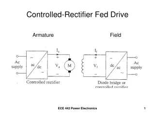
Rectifier B6- rectifier bridge InverterB6- IGBT bridge Motor Generator Thyristor Feedback Mains inverterB6- thyristor bridge Adapting transformer
Recuperative braking solution (energy feed back to mains) A fully controlled B6 thyristor bridge is operating inversely parallel to the diode rectifier Adapter transformer required (inverter operation a max=150°!) Commutation problems with mains voltage variations and frequency instabilities Mains voltage failure during the brake operation leads to commutation failure = blow up the fuses ! During generatoric operation, reactive power will increase Voltage distortion by commutation voltage dips Thyristor Feedback
Intelligent rectifier B6- IGBT bridge InverterB6- IGBT bridge motor cos j =1 generator cos j =1 cos j compensation Intelligent Rectifier – ATV 68-R
Recuperative braking solution (energy feed back to mains) Input IGBT bridge responsible for both energy directions Sinusoidal current flow in all operating states Phase shifter operation up until nominal power is possible Mains voltage failure during brake operation leads to a controlled switching off (parameter adjustable response) Emergency operation (parallel operation) with braking unit possible Intelligent Rectifier – ATV 68-R
I Diode I IGBT IGBT are pulsing at 5 (4) kHz When the IGBT is on, the current flows through it When the IGBT is switched off, the choke forces the flow of current to continue however this time through the diode. The DC link will be overcharged during this time. A change in the pulse/interval ratio regarding the voltage phase position influences the energy direction and the cos j ATV 68-R – Basic principle P = U x I P = U x I x cosj
ATV 68-R – Start sequence 1. Start command on the Intelligent Rectifier ATV 68-R The DC capacitors are pre-charged via the pre-charging circuit All ATV 68 drives are still locked. (B3.06) 2. After the pre-charging sequence the IGBTs start to work and overcharge the DC link. The IR internal voltage control is activated. Now all ATV 68 drives (linked to the DC bus) are ready to start
Size 3 4 5 2 ATV68R C10N4 C17N4 C34N4 C67N4 Input Nominal power [kVA] 100 kVA 174 kVA 338 kVA 675 kVA Nominal input current In / Un : 400 VAC 144 A 251 A 488 A 975 A In / Un : 440 VAC 131 A 228 A 441 A 885 A In / Un : 470 VAC 122 A 213 A 414 A 826 A Maximal input current for 60 s in 10 min In / Un : 400 VAC 173 A 301 A 586 A 1170 A In / Un : 440 VAC 157 A 274 A 529 A 1062 A In / Un : 470 VAC 146 A 256 A 497 A 991 A OFFER Intelligent Rectifier ALTIVAR 68R
Size 2 3 4 5 ATV68R C10N4 C17N4 C34N4 C67N4 Output Nominal power POUT [kW] 98 kW 171 kW 332 kW 663 kW Permanent output current In / Un : 650 VDC 150 A 263 A 511 A 1021 A In / Un : 720 VDC 136 A 237 A 458 A 920 A In / Un : 790 VDC 123 A 216 A 419 A 836 A Ambient conditions Working temperature [°C] 0…40°C 0…40°C 0…40°C 0…40°C Efficiency [%] > 97 % > 97 % > 97 % > 97 % Sound pressure level < 60 dB(A) < 63 dB(A) < 67 dB(A) < 68 dB(A) Protection class IP00 IP00 IP00 IP00 OFFER Intelligent Rectifier ALTIVAR 68R
Roller table Selection corresponds to the required power Device type ATV 68-R DC power Load ability ATV 68-R C17N4 171 kW 19,0 mF Device type ATV68 DC capacity ATV 68 18/22 1,1 mF Selection:ATV 68-R C17N4171kWmax. connectable DC capacity 19 mF ATV 68-R - Projecting Total of necessary active power (DC or shaft power) Caution! The motor current does not correspond to the mains current! Motor: Pout IR = Pshaft + Loss. Motor + Loss. ATVGenerator: P in IR = Pshaft – Loss. Motor – Loss. ATV – Loss. IR ATV 68 DC-capacity ATV68 18/22 = 1,1mF / 6 x 1,1mF = 6,6 mF 6 x 20 kW = 120 kW
Coiler Selection corresponds to the total DC capacity ATV68 device DC capacity ATV68 C13N4 6,3 mF ATV 68C19N4 ATV68 C13N4 ATV 68 C19N4 6,3 mF ATV 68-R device DC power Load ability ATV 68-R C17N4 171 kW 19,0 mF Selection:ATV 68-R C17N440kWmax. connectable DC capacity 19 mF ATV 68-R - Projecting In order to avoid an overload of the DC precharge circuit on ATV 68-R the total DC capacity must be determined. (Maximal permissable values see mounting instructions) DC-capacity 6,3 mF + 6,3 mF = 12,6 mF 130kW mot. – 90kW gen. = 40 kW
Length of the DC cable connection 68 – 68-R (for 4-Q combination): size 2 - size 4 max. 5 meter size 5 max. 10 meter L11 L12 + + L13 The design of a DC connection for multimotor applications has to be done with DC bus bars systems ! max. extension: 50m long (on low- inductive versions) L1 L2 L3 L1 L2 L3 PE PE L1 L2 L3 ATV 68-R - Cabling ATV68-R ATV 68 / ATV LM Intelligent Rectifier Frequency inverter Line module X1: X3: X2: max. 1,5 m X32 X31 X30 max. 5 m X31 X30 X32 U V W PE PE Motor >pDRIVE< NDS Netzdrossel / Line choke 3AC Netzeinspeisung / 3 AC mains supply
Connection/disconnection of individual inverter devices to/from the DC bus is only permitted in voltage-free state. The changed DC capacity must be notified the ATV 68-R via a digital input (see parameter group B4) The individual inverters have to be supplied by the DC bus with super-fast semiconductor fuses. Installing these fuses to an inverter device is not allowed if the common DC bus is on voltage (this would lead to a high, short-time charging current - destruction of the device Parallel operation of several ATV 68-R (at common DC bus) is not possible. (requires Master/Slave voltage controller structure, which is not qualified for redundant systems) ATV68R general information's for DC-bus bars
Controlling via an external Start/Stop signal (230V AC) on the Line Module (LM) ATV 68-R – Control Connection The external control must ensure that the start command is interrupted in the case of a fault on ATV 68-R
ATV 68-R – Control Connection Control via a 24V Start/Stop signal on the user interface of the IR A start command on the user interface (key pad, terminals or Bus)activates an output relay which triggers the start command on the line module(Terminal. 3/4) 24 V buffer voltage required on ATV 68
9 0V ATV 68R... VW3A68R4... 10 DIS Line module 11 DI1 X11 12 DI2 13 DI3 1 L 1 AC 230 V / 50 Hz 14 DI4 2 N 15 +24 3 Start 16 P24 4 K12 K11 17 P0V 5 18 6 K1 19 K12 K11 7 20 At size 5 there are no 8 terminals 6 to 10 ! K1 9 X1 10 ATV 68... 9 9 0V Run 10 10 DIS Start-Impuls 11 11 DI1 DI1 Stop-Impuls 12 12 DI2 DI2 K12 Stop 13 13 DI3 DI3 External fault Emergency Stop 14 14 DI4 DI4 15 15 +24 +24 + 16 16 P24 P24 24 V DC - 17 17 P0V P0V 18 18 Line ON 19 19 20 20 ATV 68-R – Control Connection Control via a 24V Start/Stop signal on the user interface of the ATV68...
Local Keypad Local / Remote Start Stop / Reset Reactive current higher Reactive current lower
Current actual values to the supplied mains (parameter only readable) A2.00 line frequency [Hz] A2.04 apparent power [kVA] A2.01 line voltage [V] A2.05 reactive power [kVAr] A2.02 input current [A] A2.06 cos j A2.03 actual power [kW] A2.07 phase rotation A2 Actual Value Mains