Download
1 / 18
180 likes | 327 Views
NARC: Network-Attached Reconfigurable Computing for High-performance, Network-based Applications. Chris Conger, Ian Troxel, Daniel Espinosa, Vikas Aggarwal, and Alan D. George High-performance Computing and Simulation (HCS) Research Lab Department of Electrical and Computer Engineering

E N D
NARC: Network-Attached Reconfigurable Computing for High-performance, Network-based Applications Chris Conger, Ian Troxel, Daniel Espinosa, Vikas Aggarwal, and Alan D. George High-performance Computing and Simulation (HCS) Research Lab Department of Electrical and Computer Engineering University of Florida
Outline • Introduction • NARC Board Architecture, Protocols • Case Study Applications • Experimental Setup • Results and Analysis • Pitfalls and Lessons Learned • Conclusions • Future Work
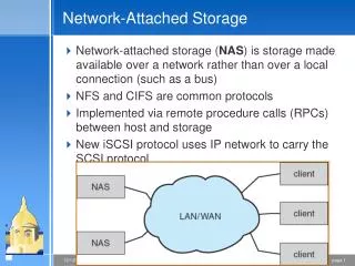
Introduction • Network-Attached Reconfigurable Computer (NARC) Project • Inspiration: network-attached storage (NAS) devices • Core concept: investigatechallenges and alternatives for enabling direct network access and control over reconfigurable (RC) devices • Method: prototype hardware interface and software infrastructure, demonstrateproof of concept for benefits of network-attached RC resources • Motivations for NARC project include (but not limited to) applications such as: • Network-accessible processing resources • Generic network RC resource, viable alternative to server and supercomputer solutions • Power and cost savings over server-based FPGA cards are key benefits • No server needed to host RC device • Infrastructure provided for robust operation and interfacing with users • Performance increase over existing RC solutions is not a primary goal of this approach • Network monitoring and packet analysis • Easy attachment; unobtrusive, fast traffic gathering and processing • Network intrusion and attack detection, performance monitoring, active traffic injection • Direct network connection of FPGA can enable wire-speed processing of network traffic • Aircraft and advanced munitions systems • Standard Ethernet interface eases addition and integration of RC devices in aircraft and munitions systems • Low weight and power also attractive characteristics of NARC device for such applications
Envisioned Applications • Aerospace & military applications • Modular, low-power design lends itself well to military craft and munitions deployment • FPGAs providing high-performance radar, sonar, and other computational capabilities • Scientific field operations • Quickly provide first-level estimations for scientific field operations for geologists, biologists, etc. • Field-deployable covert operations • Completely wireless device enabled through battery, WLAN • Passive network monitoring applications • Active network traffic injection • Distributed computing • Cost-effective, RC-enabled clusters or cluster resources • Cluster NARC devices at a fraction of cost, power, cooling • Cost-effective intelligent sensor networks • Use FPGAs in close conjunction with sensors to provide pre-processing functions before network transmission • High-performance network technologies • Fast Ethernet may be replaced by any network technology • Gig-E, Infiniband, RapidIO, proprietary communication protocols
NARC Board Architecture: Hardware • ARM9 network control with FPGA processing power (see Figure 1) • Prototype design consists of two boards, connected via cable: • Network interface board (ARM9 processor + peripherals) • Xilinx development board(s) (FPGA) • Network interface peripherals include: • Layer-2 network connection (hardware PHY+MAC) • External memory, SDRAM and Flash • Serial port (debug communication link) • FPGA control and data lines • NARC hardware specifications: • ARM-core microcontroller, 1.8V core, 3.3V peripheral • 32-bit RISC, 5-stage pipeline, in-order execution • 16KB data cache, 16KB instruction cache • Core clock speed 180MHz, peripheral clock 60MHz • On-chip Ethernet MAC layer with DMA • External memory, 3.3V • 32MB SDRAM, 32-bit data bus • 2MB Flash, 16-bit data bus • Port available for additional 16-bit SRAM devices • Ethernet transceiver, 3.3V • DM9161 PHY layer transceiver • 100Mbps, full duplex capable • RMII interface to MAC Figure 1 – Block diagram of NARC device
NARC Board Architecture: Software • ARM processor runs Linux kernel 2.4.19 • Provides TCP(UDP)/IP stack, resource management, threaded execution, Berkeley Sockets interface for applications • Configured and compiled with drivers specifically for our board • Applications written in C, compiled using GCC compiler for ARM (see Figure 2) • NARC API: Low-level driver function library for basic services • Initialize and configure on-chip peripherals of ARM-core processor • Configure FPGA (SelectMAP protocol) • Transfer data to/from FPGA, manipulate control lines • Monitor and initiate network traffic • NARC protocol for job exchange (from remote workstation) • NARC board application and client application must followstandard rules and procedures for responding to requests from a user • User appends a small header onto data (if any) containing info. about request before sending over network (see Figure 3) • Bootstrap software in on-board Flash, automatically loads and executes on power-up • Configures clocks, memory controllers, I/O pins, etc • Contacts tftp server running on network, downloads Linux and ramdisk • Boot Linux, automatically execute NARC board software contained in ramdisk • Optional serial interface through HyperTerminal for debugging/development Figure 2 – Software development process Figure 3 – Request header field definitions
NARC Board Architecture: FPGA Interface • Data communicated to/from FPGA by means of unidirectional data paths • 8-bit input port, 8-bit output port, 8 control lines (Figure 4) • Control lines manage data transfer, also drive configuration signals • Data transferred one byte at a time, full duplex communication possible • Control lines include following signals: • Clock – software-generated signal to clock data on data ports • Reset – reset signal for interface logic in FPGA • Ready – signal indicating device is ready to accept another byte of data • Valid – signal indicating device has placed valid data on port • SelectMAP – all signals necessary to drive SelectMAP configuration Figure 4 – FPGA interface signal diagram • FPGA configuration through SelectMAP protocol • Fastest configuration option for Xilinx FPGAs, protocol emulated using GPIO pins of ARM • NARC board enables remote configuration and management of FPGA • User submits configuration request (RTYPE = 01), along with bitfile and function descriptor • Function descriptor is ASCII string, formatted list of functions with associated RTYPE definition • ARM halts and configures FPGA, stores descriptor in dedicated RAM buffer for user queries • All FPGA designs must restrict use of all SelectMAP pins after configuration • Some signals are shared between SelectMAP port and FPGA-ARM link • Once configured, SelectMAP pins must remain tri-stated and unused
Results and Analysis: Raw Performance • FPGA interface I/O throughput (Table 1) • 1KB data transferred over link, timed • Measured using hardware methods • Logic analyzer – to capture raw link data rate, divide data sent by time from first clock to last clock (see Figure 9) • Performance lower than desired for prototype • Handshake protocol may add unnecessary overhead • Widening data paths, optimizing software routine will significantly improve FPGA I/O performance • Network throughput (Table 2) • Measured using Linux network benchmark IPerf • NARC board located on arbitrary switch within network, application partner is user workstation • Transfers as much data as possible in 10 seconds, calculates throughput based on data sent divided by 10 seconds • Performed two experiments with NARC board serving as client in one run, server in other • Both local and remote (remote location ~400 miles away, at Florida State University) IPerf partner • Network interface achieves reasonably good bandwidth efficiency • External memory throughput (Table 3) • 4KB transferred to external SDRAM, both read and write • Measurements again taken using logic analyzer • Memory throughput sufficient to provide wire-speed buffering of network traffic • On-chip Ethernet MAC has DMA to this SDRAM • Should help alleviate I/O bottleneck between ARM and FPGA Figure 9 – Logic analyzer timing Table 1 – FPGA interface I/O performance Table 2 – Network throughput Table 3 – External SDRAM throughput
Results and Analysis: Raw Performance • Reconfiguration speed • Includes time to transfer bitfile over network, plus time to configure device (transfer bitfile from ARM to FPGA), plus time to receive acknowledgement • Our design currently completes a user-initiated reconfiguration request with a 1.2MB bitfile in 2.35sec • Area/resource usage of minimal wrapper for Virtex-II Pro FPGA • Stats on resource requirements for a minimal design to provide required link control and data transfer in an application wrapper are presented below: • Design implemented on older Virtex-II Pro FPGA • Numbers to right indicate requirements for wrapper only, un-used resources available for use in user applications • Extremely small footprint! • Footprint will be even smaller on larger FPGA Device utilization summary: -------------------------------------------------------- Selected Device : 2vp20ff1152-5 Number of Slices: 143 out of 9280 1% Number of Slice Flip Flops: 120 out of 18560 0% Number of 4 input LUTs: 238 out of 18560 1% Number of bonded IOBs: 24 out of 564 4% Number of BRAMs: 8 out of 88 9% Number of GCLKs: 1 out of 16 6%
Case Study Applications • Clustered RC Devices: N-Queens • HPC application demonstrating NARC board’s role as generic compute resource • Application characterized by minimal communication, heavy computation within FPGA • NARC version of N-Queens adapted from previously implemented application for PCI-based Celoxica RC1000 board housed in a conventional server • N-Queens algorithm is a part of the DoD high-performance computing benchmark suite and representative of select military and intelligence processing algorithms • Exercises functionality of various developed mechanisms and protocols for job submission, data transfer, etc. on NARC • User specifies a single parameter N, upon completion the algorithm returns total number of possible solutions • Purpose of algorithm is to determine how many possible arrangements of N queens there are on an N×N chess board, such that no queen may attack another (see Figure 5) • Results are presented from both NARC-based execution and RC1000-based execution for comparison Figure c/o Jeff Somers Figure 5 – Possible 8x8 solution
Case Study Applications • Network processing: Bloom Filter • This application performs passive packet analysis through use of a classification algorithm known as a Bloom Filter • Application characterized by constant, bursty communication patterns • Most communication is Rx over network, transmission to FPGA • Filter may be programmed or queried • NARC device copies all received network frames to memory, ARM parses TCP/IP header and sends it to Bloom Filter for classification • User can send programming requests, which include a header and string to be programmed into Filter • User can also send result collection requests, which causes a formatted results packet to be sent back to the user • Otherwise, application constantly runs, querying each header against the current Bloom Filter and recording match/header pair information • Bloom Filter works by using multiple hash functions on a given bit string, each hash function rendering indices of a separate bit vector (see Figure 6) • To program, hash inputted string and set resulting bit positions as 1 • To query, hash inputted string, if all resulting bit positions are 1 the string matches • Implemented on Virtex-II Pro FPGA • Uses slightly larger, but ultimately more effective application wrapper (see Figure 7) • Larger FPGA selected to demonstrate interoperability with any FPGA Figure 6 – Bloom Filter algorithmic architecture Figure 7 – Bloom Filter implementation architecture
Experimental Setup • N-Queens: Clustered RC devices • NARC device located on arbitrary switch in network • User interfaces through client application on workstation, requests N-Queens procedure • Figure 8 illustrates experimental environment • Client application records time required to satisfy request • Power supply measures current draw of active NARC device • N-Queens also implemented on RC-enabled server equipped with Celoxica RC1000 board • Client-side function call to NARC board replaced with function call to RC1000 board in local workstation, same timing measurement • Comparison offered in terms of performance, power, cost • Bloom Filter: Network processing • Same experimental setup as N-Queens case study • Software on ARM co-processor captures all Ethernet frames • Only packet headers (TCP/IP) are passed to FPGA • Data continuously sent to FPGA as packets arrive over network • By attaching NARC device to switch, limited packets can be captured • Only broadcast packets and packets destined for the NARC device can be seen • Dual-port device could be inserted in-line with network link, monitor all flow-through traffic Figure 8 – Experimental environment
Results and Analysis: N-Queens Case Study • First, consider an execution time comparison between our NARC board and a PCI-based RC card (see Figure 10a and 10b) • Both FPGA designs clocked at 50MHz • Performance difference is minimal between devices • Being able to match performance of PCI-based card is a resounding success! • Power consumption and cost of NARC devices drastically lower than that of server with RC card combos • Multiple users may share NARC device, PCI-based cards somewhat fixed in an individual server • Power consumption calculated using following method • Three regulated power supplies exist in complete NARC device (network interface + FPGA board): 5V, 3.3V, 2.5V • Current draw from each supply was measured • Power consumption is calculated as sum of V×I products of all three supplies Figure 10 – Performance comparison between NARC board and PCI-based RC card on server
Results and Analysis: N-Queens Case Study • Figure 11 summarizes the performance ratio of N-Queens between both NARC and RC-1000 platforms • Consider Table 4 for a summary of cost and power statistics • Unit price shown excluding cost of FPGA • FPGA costs offset when compared to another device • Price shown includes PCB fabrication, component costs • Approximate power consumption drastically less than server + RC-card combo • Power consumption of server varies depending on particular hardware • Typical servers operate off of 200-400W power supplies • See Figure 12 for example of approximate power consumption calculation Figure 11 – Power consumption calculation Table 4 – Price and power figures for NARC device P = (5V)(I5) + (3.3V)(I33) + (2.5V)(I25) I5 ≈ 0.2A ; I33 ≈ 0.49A ; I25 ≈ 0.27A P = (5)(.2) + (3.3)(.49) + (2.5)(.27) =3.28W Figure 12 – Power consumption calculation
Results and Analysis: Bloom Filter • Passive, continuous network traffic analysis • Wrapper design was slightly larger than previous minimal wrapper used with N-Queens • Still small footprint on chip, majority of FPGA remains for application • Maximum wrapper clock frequency 183 MHz, should not limit application clock if in same clock domain • Packets received over network link are parsed by ARM, with TCP/IP header saved in buffer • Headers sent one-at-a-time as query requests to Bloom Filter (FPGA), when query finishes another header will be de-queued if available • User may query NARC device at any time for results update, program new pattern • Figure 13 shows resource usage for Virtex-II Pro FPGA • Maximum clock frequency of 113MHz • Not affected by wrapper constraint • Significantly faster computation speed than FPGA-ARM link communication speed • FPGA-side buffer will not fill up, headers are processed before next header transmitted to FPGA • ARM-side buffer may fill up under heavy traffic loads • 32MB ARM-side RAM gives large buffer Device utilization summary: ------------------------------------------------------- Selected Device : 2vp20ff1152-5 Number of Slices: 1174 out of 9280 13% Number of Slice Flip Flops: 1706 out of 18560 9% Number of 4 input LUTs: 2032 out of 18560 11% Number of bonded IOBs: 24 out of 564 4% Number of BRAMs: 9 out of 88 10% Number of GCLKs: 1 out of 16 6% Figure 13 – Device utilization statistics for Bloom Filter design
Pitfalls and Lessons Learned • FPGA I/O throughput capacity remains persistent problem • One motivation for designing custom hardware is to remove typical PCI bottleneck and provide wire-speed network connectivity for FPGA • Under-provisioned data path between FPGA and network interface restricts performance benefits for our prototype design • Luckily, this problem may be solved through a variety of approaches • Wider data paths (16-bit, 32-bit) double or quadruple throughput, at expense of higher pin count • Use of higher-performance co-processor capable of faster I/O switching frequencies • Optimized data transfer protocol • Having co-processor in addition to FPGA to handle network interface is vital to success of our approach • Required in order to permit initial remote configuration of FPGA, as well as additional reconfigurations upon user request • Offloading network stack, basic request handling, and other maintenance-type tasks from FPGA saves significant amount of valuable slices for user designs • Drastically eases interfacing with user application on networked workstation • Active co-processor for FPGA applications, e.g. parsing network packets as in Bloom Filter application
Conclusions • A novel approach to providing FPGAs with standalone network connectivity has been prototyped and successfully demonstrated • Investigated issues critical to providing remote management of standalone NARC resources • Proposed and demonstrated solutions to discovered challenges • Performed pair of case studies with two distinct, representative applications for a NARC device • Network-attached RC devices offer potential benefits for a variety of applications • Impressive cost and power savings over server-based RC processing • Independent NARC devices may be shared by multiple users without moving • Tightly coupled network interface enables FPGA to be used directly in path of network traffic for real-time analysis and monitoring • Two issues that are proving to be a challenge to our approach include: • Data latency in FPGA communication • Software infrastructure required to achieve a robust standalone RC unit • While prototype design achieves relatively good performance in some areas, and limited performance in others, this is acceptable for concept demonstration • Fairly complex board design; architecture and software enhancements in development • As proof of “NARC” concept, important goal of project was achieved in demonstration of an effective and efficient infrastructure for managing NARC devices
Future Work • Expansion of network processing capabilities • Further development of packet filtering application • More specific and practical activity or behavior sought from network traffic • Analyze streaming packets at or near wire-speed rates • Expansion of Ethernet link to 2-port hub • Permit transparent insertion of device into network path • Provide easier access to all packets in switched IP network • Merging FPGA with ARM co-processor and network interface into one device • Ultimate vision for NARC device • Will restrict number of different FPGAs which may be supported, according to chosen FPGA socket/footprint for board • Increased difficulty in PCB design • Expansion to Gig-E, other network technologies • Fast Ethernet targeted for prototyping effort, concept demonstration • True high-performance device should support Gigabit Ethernet • Other potential technologies include (but not limited to) InfiniBand, RapidIO • Further development of management infrastructure • Need for more robust control/decision-making middleware • Automatic device discovery, concurrent job execution, fault-tolerant operation