Download
1 / 35
350 likes | 481 Views
South Africa Power Generation. Group Members. Steven Bularca CS & CpE. Genesh Chen- Shue EE . Aldo Puente EE & CpE. Armel Nidjeu EE. Motivation.

E N D
Group Members Steven Bularca CS & CpE Genesh Chen-Shue EE Aldo Puente EE & CpE Armel Nidjeu EE
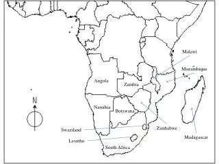
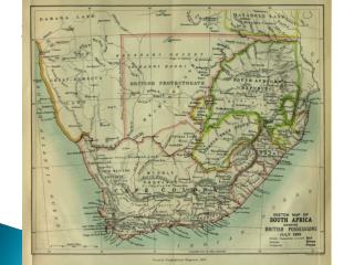
Motivation • Great need of electricity in the small South African community of the Pomolong Township, which is occupied by the less fortunate people of South Africa due to the aftereffects of apartheid. • They are cut off from the rest of the world because they do not have electricity that will enable them to use electronic devices such computers, cell phones, and TVs. • Even if they could afford the cost of power, the township is not close to the power grid.
Goals and Objectives • Some of the sources that were considered were wind, hydro, solar, and mechanical/kinetic energy. • The absolute most important objective is safety, because ensuring that the system is safe protects lives and mitigates damages. • A major objective of this project is for the power generating system to be extremely efficient, because the resources are scarce and utilizing every bit of energy gives the townspeople more time to enjoy the electricity. • Keeping in mind the technology aptitude of the users, ease of use became an unavoidable objective. • One of the objectives is to successfully capture as much sunlight energy as possible. This will be done through a MPPT charge controller system. • Deep cycle batteries are what are planned to be implemented for the project, because deep cycle batteries are made to be completely drained. • The inverter will take the power from the charged batteries in the form of a DC input. desired. • A robust, weather resistant, and safe enclosure to keep the entire system secure is a crucial part of the project.
Energy • We chose to use renewable energy over fossil or nuclear energy because the latter resources were not obtainable • The renewable energy we chose to use was solar because it was scalable and could produce the most power given the limitation of funding. • Power for solar panels cost around 1-2 dollars per Watt. For example, 2 305W Helios PV panels cost $752, making the cost per watt for that particular panel $1.23 per Watt. • South Africa Irradiation levels are high • The other renewable energy source that was considered was wind, but based on research, the cost for a wind turbine that would generate enough power was out of our budget range
H-Bridge P-Channel N-Channel • P-channel devices have a higher ‘on’ resistance so there is greater power loss • N-channel device will require a driver with a bootstrap capacitor to generate the higher voltage above the switching voltage of 230V to turn on the device We decided to use IRFP260N-Channel MOSFETs, because efficiency was a stronger factor than convenience.
Output filter • System is filtered by an RC Low Pass Filter with: • A 200V 1800uf electrolytic capacitor • A Metalized Polypropylene Film Capacitor.
Inverter PCB We used Eagle for the PCB Design and Ordered the PCB from Hackvana.com
Battery Considerations We had to calculate the amount of charge capacity the batteries should hold so we use Peukert’s Law: t=H(C/IH)^k Peukert's Law expresses the capacity of a battery in terms of discharge rate, where t is the total time to discharge the battery, k is the Peukert constant, I is the discharge current, C is the rated capacity at the discharge rate, and H is the rated discharge time. We Calculated the proper Ah parameter to be around 75Ah. Considering the different battery types, we decided on flooded batteries because of the vast amounts available in the world. If the batteries needed to be replaced, we wanted the option that is the easiest to replace while maintaining a low cost.
Issues • Charge Controller • Finding an Inductor that can handle the current • Buck-Boost converter • Inverter • Boost Converter • Isolation of power lines from control line • Other Issues • Ventilation of Batteries • Sponsors