Download
1 / 33
330 likes | 420 Views
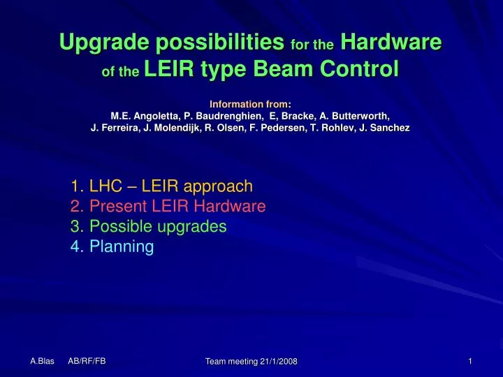
Upgrade possibilities for the Hardware of the LEIR type Beam Control Information from : M.E. Angoletta, P. Baudrenghien, E, Bracke, A. Butterworth, J. Ferreira, J. Molendijk, R. Olsen, F. Pedersen, T. Rohlev, J. Sanchez. LHC – LEIR approach Present LEIR Hardware Possible upgrades

E N D
Upgrade possibilities for the Hardwareof the LEIR type Beam ControlInformation from:M.E. Angoletta, P. Baudrenghien, E, Bracke, A. Butterworth,J. Ferreira, J. Molendijk, R. Olsen, F. Pedersen, T. Rohlev, J. Sanchez • LHC – LEIR approach • Present LEIR Hardware • Possible upgrades • Planning Team meeting 21/1/2008
Beam Control Typical architecture Both the LHC and LEIR system start with the same initial structure Typical constraint for the signal processing delay: Loop computation time + Hdw delay < 1/(8.Fmod) [phase lag @ max Fmod < π/4] < 21 us for PSB & LEIR phase loop (3.Fs=6kHz) Team meeting 21/1/2008
Beam Control Signal processing In LEIR the FPGA-DSP-FPGA triptych is always used In LHC it depends. Note that using the DSP in a loop implies major timing problems when a precise loop delay is required (TFB, 1TFB) (see example in Elettra) Team meeting 21/1/2008
Beam Control Board layout • Interconnect architecture shared by the LHC and LEIR hardware • The Central FPGA (fpga array in Leir) routs the data from and to the different locations • The special function board can be in the form of an on-board specific circuit, a daughter cards or a dedicated VME board Team meeting 21/1/2008
Beam Control Clocking LHC: A central VCO, controlled by a central processor, outputs the rf (400MHz +/- e) feeding the cavity. This rf signal is used to create the 380, 80, 40, 20, Frev which are dispatched within the hardware. LEIR: A central DDS, controlled by a central processor, outputs the tagged rf clock distributed to all rf sources or demod inputs. (+) Absolute phase control over distant inputs/outputs without (except practical) limitations on their number. (+) Synchronous change of parameters on all boards. (+) The Clock harmonic can be changed on the fly (factor 1, 2, 4 and 8) for use on a wide frequency span (factor 16) (+) synchronous signal acquisition Team meeting 21/1/2008
Beam Control Hardware standards LHC: VME 64 crate, h: 9U 4 front slots, 160 mm depth with standard P1/P2 bus 15 front slots, 220 mm depth with dedicated P2 bus Spec. power supplies setup 6 kCHF + 10 kCHF CPU LEIR: VME 64X crate, h: 9U 23 front slots, 160 mm depth 23 back slots, 160 mm depth All standard P0, P1, P2 connectors Standard Power supply 8 kCHF + 10 kCHF CPU Team meeting 21/1/2008
Beam Control Communication links Team meeting 21/1/2008
FPGA comparison Team meeting 21/1/2008
DSPs comparison Team meeting 21/1/2008
DSP chip ADSP 21160M (Leir at present) 80 MHz, 4Mbit on chip SRAM, 2.5V core Team meeting 21/1/2008
DSP chip Possible LEIR upgrade ADSP 21160N Same as M version except 20% faster (100 MHz) and 1.8V core Team meeting 21/1/2008
DSP chip Tiger Sharc ADSP-TS101 (LHC) Team meeting 21/1/2008
Leir BC <-> LHC BC Team meeting 21/1/2008
Leir BC <-> LHC BC • LEIR • Pros: • Standard VME 64X crate with front and rear access • Very modular approach; with 3 DC (DDC, SDDS, MDDS), 1 MB and 1 RTM, you have the base for all type of applications (except yet for 1TFB and TFB) • Synchronous control over all the hardware • LHC • Pros: • Power supplies adapted to low noise requirements • More up-to-date circuits and connectors Team meeting 21/1/2008
Leir Beam Control Clock core Output rf frequency <12 MHz (for a swept frequency - without up-conversion) <25 MHz at fixed frequency (without up-conversion) Limitations due to the basic structure (max ADC DAC sampling + tag creation circuit) Team meeting 21/1/2008
Leir Beam Control Acquisition Team meeting 21/1/2008
Leir Beam Control Outputs Team meeting 21/1/2008
Beam Control General architecture (LEIR) Team meeting 21/1/2008
Beam Control Constraints Data flow Rule of thumb: The loop will be sufficiently stable if its delay leads to a phase lag < p/4 at the unity loop gain frequency Loop computation time + Hdw delay < [1/(8.Fmod)] < 21 us for PSB & LEIR (3.Fs=6kHz) < 26 us for PS (3.Fs=4.8 kHz) In LEIR, the in-loop DSP is sampling the data every TS-DSP = 12.5 us (80 kHz). The loop delay within the DSP = import data from DDC (<50ns) + compute error (<7us) + send error to MDDS or SDDS (via another DSP or not < 150 ns) + equivalent 1st order S/H delay (6.25 us) => ≈14us delay within the DSP With a 80 kHz DSP sampling clock, an averaging (CIC) of 1000 80-MHz-samples in the DDC would be adequate. We actually use 256, which means <6.4 us extra delay. This means that we are approaching the reasonable limits required for the LEIR and PSB phase loop. The DSP process time in LEIR is the most time consuming and multiplying by a factor 2 this process speed would almost double the possible bandwidth. Team meeting 21/1/2008
Leir Beam Control Data Flow Here, the central DSP B has all its links ports used (limiting factor) In case of more DSP boards, we would need to add links to the leading DSP or implement a pipe lined communication protocol through DSP boards or make all DSPs share a single bus with a communication protocol to be defined. In terms of bandwidth, A gigabit link could replace the link ports and the DSP-to-daughter card link Team meeting 21/1/2008
Leir Beam Control Daughter cards The present DDC (ADC) and SDDS (DAC) daughter cards having 4 channels are limited in terms of FPGA logic cells. The signal monitoring circuit could not be implemented. The 4 channels of the DDC need to share 2 LOs The DDC FIR could not be implemented The present chip: AlteraStratix EP1S20F 484C5 should be replaced with a version with 6 times more logic elements to have a 50% loading at most. 18k LE -> 110 k LE and twice as much RAM (1.6 Mb -> 3.2 Mb) and same I/O: 361. The Stratix 3 EP3SL150 can do the job: 142 kLE, 5.5 Mb, 480 or 736 I/O, 1400 euros (Spoerle) Team meeting 21/1/2008
DSP board Background 04/2002 Original design by Joe Delong (BNL) 03/2005 Original version imported in the CERN database (EDA 00990) and called version 1 13 units constructed and tested. Followed-up by J. Ferreira-Bento. 08/2006Upgrade to version 3 by Tony Rohlev, after a faulty version 2 which had a bad set of connections on a FPGA Main improvements: latched registers interfacing the VME bus + adequate power-up sequence. (see AB-Note-2007-031-RF for a detailed description of the modifications) 09/2007 Version 4. Cleaned-up version : removed 4 daughter card connectors (only 2 DC slots now), 1 FPGAs, the Event link circuit, the link-port connections to the DC connectors (reflections), Added DSP address bus lines 15-19 to the DC to avoid paging of the SRAM address + allow use of DMA (DMA lines added) + use of delayed SELN bits for the register address decoding, all 16 RTM signal connected (6 before). Team meeting 21/1/2008
DSP board Version 1 Block Diagram Problem: When the DSP SRAM is controlled by the VME bus The DSP is blocked Team meeting 21/1/2008
DSP board Version 3 Block Diagram Here the DSP SRAM data can be stored on the VME bus to allow the “long” ~1us VME Read process while letting the DSP run Team meeting 21/1/2008
DSP board Some limitations • DSP blocked when the VME (which has priority) accesses the DSP SRAM (improved in version 3), Problem solved in Leir with pre-defined time slots for each access. Not convenient for long cycling machine as AD where operational data should be accessed during the cycle. • Bus lines arbitration by 5 (4 in V4) distinct FPGAs => not flexible and uneasy to maintain • DSP limited computing power. Impairs the rf loops pipe-line delay and signal quality (aliases), • requires assembly coding (instead of a more universal C coding) • DSP configuration device not accessible via VME for remote programming, • nor daughter card JTAG programming. • Only 6 timing (or digital) inputs from J2/P2 connector (RTM allows 16) (solved in V4) • 4 MB DSP memory + 4 MB for measurement memory foreseen to be too little (-> 32 MB total) • VME base address selected by FPGA coding (-> put switches also) Team meeting 21/1/2008
LHC tuner loop DSP board • The Tiger Sharc (tested) circuit can be re-used. • For the FPGA there might be better choices in other circuit using Virtex 4. Team meeting 21/1/2008
Proposed upgrade for the LEIR type DSP mother board Team meeting 21/1/2008
Leir Type DSP BC upgrade. Summary • Some CadenceTM blocks can be used from LHC designs with improved specs (tiger shark) + Gigabit link + general interconnect philosophy • The Virtex 4 or Stratix 2 circuits could also be imported but we should move to Virtex 5 or Stratix 3 (lower power dissipation 65nm, serial link interface not bugged + higher performances). To be used on DSP board and daughter cards. • The standard VME 64X remains a good choice. Noise issues have still to be checked for AD (linear Power Supplies). • The tagged clock and its distribution are a real plus for synchronous operation but the actual connectors are too fragile and could be replaced the RJ45 model used in LHC rf. • Add all the hardware details mentioned on the previous slide. Team meeting 21/1/2008
Leir Type DSP BC upgrade. Possible scenario • Install a test beam control in the PSB for the 2008 run, using our present stock of Hardware. A few units are still to be tested. Can be ready in mid 2008. • Analysis of the software requirements if using a new DSP (MEA) • Definition of an adequate inter-DSP link (h/w + protocol) (1man.month) • Update the mother board with all the new features keeping the compatibility with the present daughter cards. 8 man-month for the hardware, 6 man-month for the software + 40 kCHF. Ideally the software should be finished before we start the hardware. • Update of the daughter boards (DDC + SDDS): 3 man-month x 2 for the hardware + 1 man-month x 2 for the software + 40 CHF -> 1 working prototype for each function. • Total: 2 man-year + 80 kCHF for a “final” DSP beam control prototype hopefully fulfilling the requirements of all the Injectors on the Meyrin site. Team meeting 21/1/2008
DSP BC upgrade Generic view Team meeting 21/1/2008
Leir Beam Control Team meeting 21/1/2008
Misc • Arctan computation: FPGA Cordic John: 17 clock periods for a 16 bit resolution DSP Pawel: 33 clock period for a 18 bit resolution Team meeting 21/1/2008