Download
1 / 44
600 likes | 1.83k Views
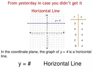
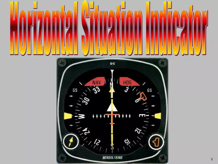
Horizontal Situation Indicator. TERMINAL LEARNING OBJECTIVE:. ENABLING LEARNING OBJECTIVE A. KCS-55A system Supporting: King/ Bendix : KI 525A (HSI) King/ Bendix : KNI 582 (RMI). Directional Gyro. Magnetic Slaving Transmitter. KA-51B Slaving Control. Aeronautical Information Manual

E N D
KCS-55A system Supporting: King/Bendix: KI 525A (HSI) King/Bendix: KNI 582 (RMI)
Directional Gyro Magnetic Slaving Transmitter KA-51B Slaving Control
Aeronautical Information Manual Explanation of Changes (Change 1) Effective: 26 Jul 12 This change explains why slaved compass systems may be susceptible to heading errors on the ground and alerts pilots to the fact that the system’s erroneous heading may not self-correct. It also offers mitigation strategies to avoid a possible heading misalignment at takeoff. Para 1−1−7 d
d. Aircraft equipped with slaved compass systems may be susceptible to heading errors caused by exposure to magnetic field disturbances (flux fields) found in materials that are commonly located on the surface or buried under taxiways and ramps. These materials generate a magnetic flux field that can be sensed by the aircraft’s compass system flux detector or “gate”, which can cause the aircraft’s system to align with the material’s magnetic field rather than the earth’s natural magnetic field. The system’s erroneous heading may not self-correct. Prior to take off pilots should be aware that a heading misalignment may have occurred during taxi. Pilots are encouraged to follow the manufacturer’s or other appropriate procedures to correct possible heading misalignment before take off is commenced.
Lubber Line Compass Card Symbolic Aircraft Course Select Knob Selected Course Pointer Deviation Scale VOR or RNAV (GPS) or LOC Deviation Bar
Heading Select Bug Heading Select Knob To/FromIndicator (NOT used in LOC or ILS modes) Dual Glideslope ChartreusePointers Glideslope Deviation Scale
HDG NAV WARNING FLAG (NAV) WARNING FLAG (HDG) Abnormal Indications GLIDESLOPE POINTERS NOT VISIBLE DURING ILS
VHF Omnidirectional Test Signal (VOT) Correct indication - FROM with 360 course selected Excessive error 5 deg right Tolerance +4 Transmits only the 360o Radial. Generally on 108.0 MHz Ref: 14 CFR 91.171(b)1
VOR Ground Checkpoint Tolerance +4. Ground Checkpoints are not published in DOD FLIP but are published on Airport Diagrams and in the FAA Airport/Facility Directory. 2 7 066oR OZR 111.2 066R VOL 14 Page: 80
AP-1 AIRBORNE
Airborne VOR Receiver Checkpoint 1. Published in DOD FLIP AP/1 2. Tolerance ± 6º 2000 MSL 7.4 NM R - 314 Enterprise Muni / VOR
DUAL VOR RECEIVER CHECKNav 1 (Garmin 430W) and Nav 2 (KX-165) 1. Center both HSI deviation bars. 2. Tolerance: Selected course Pointers must be within 4o of each other. Ref: FM 3-04.240 Para 7-41 AIM Para 1-1-4
Rotate Selected Course Pointer until deviation bar centers. TO/FROM Indicator Selected COURSE Cardinal directions RADIAL - read opposite TO/FROM indicator Radials either side of current position 180° radial 4° LEFT. The aircraft is on the 176° radial ORIENTATION
Will selected course take you toward or away from station? ORIENTATION What is your position (radial)?
Will selected course take you toward or away from station? ORIENTATION What is your position (radial)?
Intercept the 190 degree radial inbound. 1. Locate radial to be intercepted (190). 2. Convert to course. 3. Rotate course selector knob until point of course selector shows new course (010°). 4. Turn TOWARD the course deviation indicator until course selector is at the 45° index. 5. As deviation bar centers, turn to new course.
Intercept the 210 degree radial inbound EXPEDITE. 1. Locate radial to be intercepted (210). 2. Convert to course. 3. Rotate course selector knob until point of course selector points to new course (030°). 4. Turn TOWARD course deviation indicator until course selector is at the 90° index. 5. As deviation bar centers, turn to new course.
Intercept the 025 degree Radial Outbound 1. Locate radial / course to be intercepted (025°). 2. Rotate course selector knob until point of course selector shows new course (025°). 3. Turn TOWARD course deviation indicator until course selector is at the 45° index. 4. As deviation bar centers, turn to new course.
Fix Clios Intersection EUF 109.20 R-249 R-229 OZR 111.20
NAV STATION PASSAGE
Tracking the MGM 126 radial inbound (Airspeed 100 knots) 2nd TRIAL CORRECTION INITIAL CORRECTION 1st TRIAL CORRECTION 1st TRIAL CORRECTION TOO SMALL REPEAT INITIAL CORRECTION
Tracking the MGM 126 radial inbound (Airspeed 100 knots) 2nd TRIAL CORRECTION INITIAL CORRECTION 1st TRIAL CORRECTION TURN PARALLEL TO COURSE 1st TRIAL CORRECTION TOO LARGE
HSI Deviation Scale - 0.3 Nm + 10o - 5 Nm -1 Nm - 2 1/2o +5 Nm + 0.3 Nm + 2 1/2o -10o + 1 Nm • LOC (Localizer) = + 2 ½ degrees • VOR = + 10 degrees • GPS = • Enroute = + 5 Nm* • Terminal Area = + 1 Nm • Approach = + 0.3 Nm * Flight line IP’s usually select 2 Nm; however this is for RNP (Required Navigation Performance) certification which the A/C is NOT certified for.
Bendix-King KI-825 Electronic Horizontal Situation Indicator (EHSI) As of: Oct 2013 6 IFR TH-67’s are equipped with the KI-825. Installations are being completed when aircraft are in phased maintenance. (This is NOT progressing quickly as from Jan 2013 – Oct 2013 only one KI-825 was installed) Simulators will be updated when 50% of our fleet has KI-825’s installed. (Circa year 2033) Our Fleet: 65 IFR TH-67’s For more info: http://www.seaerospace.com/king/kinggra/ki825pg.pdf
BREAK TIME