Download
1 / 60
610 likes | 746 Views
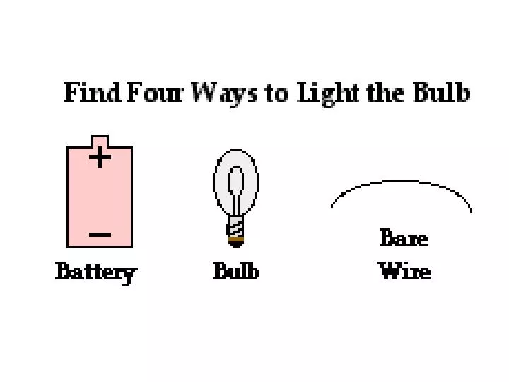
In conclusion, there are two requirements which must be met in order to establish an electric circuit. The requirements are:

E N D
In conclusion, there are two requirements which must be met in order to establish an electric circuit. The requirements are: • There must be an energy supply capable doing work on charge to move it from a low energy location to a high energy location and thus creating an electric potential difference across the two ends of the external circuit. • There must be a closed conducting loop in the external circuit which stretches from the high potential, positive terminal to the low potential negative terminal.
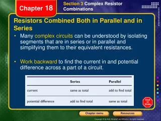
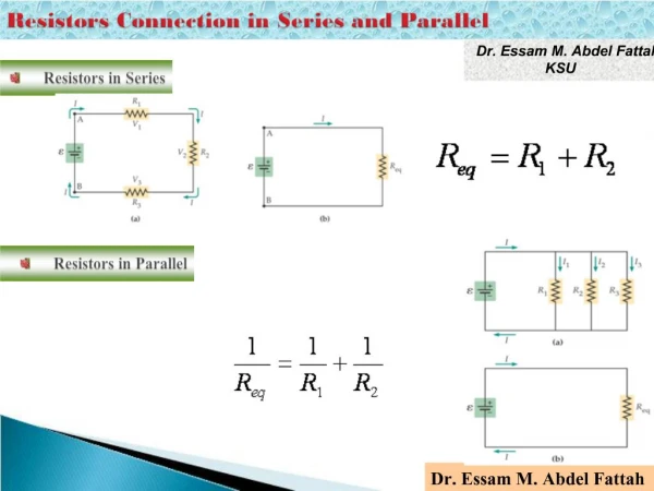
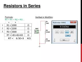
RESISTORS IN SERIES - In a series circuit, the current is the same at all points along the wire. IT = I1 = I2 = I3 - An equivalent resistance is the resistance of a single resistor that could replace all the resistors in a circuit. The single resistor would have the same current through it as the resistors it replaced. RE = R1 + R2 + R3 - In a series circuit, the sum of the voltage drops equal the voltage drop across the entire circuit. VT = V1 + V2 + V3
12.4 Two resistances of 2 Ω and 4 Ω respectively are connected in series. If the source of emf maintains a constant potential difference of 12 V. a. Draw a schematic diagram with an ammeter and a voltmeter.
12.4 Two resistances of 2 Ω and 4 Ω respectively are connected in series. If the source of emf maintains a constant potential difference of 12 V. b. What is the current delivered to the external circuit? Re= R1 + R2 = 2 + 4 = 6 Ω = 2 A c. What is the potential drop across each resistor? V1 = I R1 = 2(2) = 4 V V2 = I R2 = 2(4) = 8 V
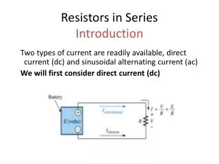
PARALLEL CIRCUITS - In a parallel circuit, each resistor provides a new path for electrons to flow. The total current is the sum of the currents through each resistor. IT = I1 + I2 + I3 - The equivalent resistance of a parallel circuit decreases as each new resistor is added. - The voltage drop across each branch is equal to the voltage of the source. VT = V1 = V2 = V3
KIRCHHOFF’S LAWS Anelectrical networkis a complex circuit consisting ofcurrent loops. Kirchhoff developed a method to solve this problems using two laws. Law 1.The sum of thecurrents enteringa junction is equal to the sum of thecurrents leavingthat junction. This law is a statement ofcharge conservation.
A junction (j)refers to any point in the circuit where two or three wires come together. j
KIRCHHOFF’S LAWS Law 2.The sum of theemfsaround any closed current loop is equal to the sum of all theIR dropsaround that loop. (Ohm’s Law:V = IR) This law is a statement ofenergy conservation.
12.5 The total applied voltage to the circuit in the figure is 12 V and the resistances R1, R2 and R3are 4, 3 and 6 Ω respectively. a. Determine the equivalent resistance of the circuit. R2 and R3 are in parallel (RP) Rp= 2 Ω RP and R1 are in series Re= 4 + 2 = 6 Ω
b. What is the current through each resistor? I1 = 2 A (series) V1 = I1R1 = 2(4) = 8 V = 2 A The voltage across the parallel combination is therefore: 12 - 8 = 4 V each = 0.67 A = 1.33 A
12.6 Find the equivalent resistance of the circuit shown. 1 and 2 are in series: 1+ 2 = 3 Ω this combination is in parallel with 6: RP = 2 Ω this combination is in series with 3:2 + 3 = 5 Ω this combination is in parallel with 4: RP = 2.22 Ω = Req
12.7 A potential difference of 12 V is applied to the circuit in the figure below. a. Find the current through the entire circuit R1and R2are in parallel: RP= 2 Ω This combination is in series with R3: 2 + 4 = 6 Ω This combination is now in parallel with R4: = 3 Ω = Req
= 4 A b. Find the current through each resistor. IT = I3 + I4 I3 = IT - I4 = 4 - 2 = 2 A = 2 A
The voltage for the parallel combination is: V' = V - I3 R3 = 12 - (2)(4) = 4 V = 1 A I2= 2 - 1 = 1 A
EMF AND TERMINAL POTENTIAL DIFFERENCE Every source of emf(Є) has an inherent resistance called internal resistance represented by the symbol r. This resistance is a small resistance in serieswith the source of emf. The actual terminal voltage VT across a source of emf with an internal resistance is given by: VT = Є - I r Units: Volts (V)
12.8 A load resistance of 8 Ω is connected to a battery whose internal resistance is 0.2 Ω a. If the emf of the battery is 12 V, what current is delivered to the load? Є = 12 V RL = 8 Ω r = 0.2 Ω = 1.46 A b. What is the terminal voltage of the battery? VT = Є - I r = 12 - 1.46(0.2) = 11.7 V
12.9 a. Determine the total current delivered by the source of emf to the circuit in the figure. V = 24 V. The resistances are 6, 3, 1, 2 and 0.4 Ω respectively. R1and R2are in parallel: RP= 2 Ω this combination is in series with R3: 2 + 1 = 3 Ω this combination is now in parallel with R4: RP = 1.2 Ω
finally the internal resistance r is in series giving the equivalent resistance: Req= 1.2 + 0.4 = 1.6 Ω = 15 A
b. What is the current through each resistor? VT = Є - I r = 24 - 15(0.4) = 18 V V4 = VT = 18 V I3 = IT - I4 = 15 - 9 = 6 A V3 = I3R3 = 6(1) = 6 V = 9 A V1 = V2 = 18 - 6 = 12 V each = 4 A = 2 A
A + Rheostat Emf V - Source of EMF Rheostat Voltmeter Ammeter Ammeters and Voltmeters
0 10 10 20 20 N S Galvanometer The galvanometer uses torque created by small currents as a means to indicate electric current. A current Ig causes the needle to deflect left or right. Its resistance is Rg. The sensitivity is determined by the current required for deflection.
Rg Ig I Rs Is Operation of an Ammeter The galvanometer is often the working element of both ammeters and voltmeters. A shunt resistance in parallel with the galvanometer allows most of the current I to bypass the meter. The whole device must be connected in series with the main circuit. I = Is + Ig The current Igis negligible and only enough to operate the galvanometer. [ Is >> Ig ]
Rg Ig Rm I VB Operation of an Voltmeter The voltmeter must be connected in parallel and must have high resistance so as not to disturb the main circuit. A multiplier resistance Rmis added in series with the galvanometer so that very little current is drawn from the main circuit. The voltage rule gives: VB = IgRg + IgRm
CAPACITORS IN SERIES AND PARALLEL These are the symbols used in different arrangements of capacitors:
CAPACITORS IN SERIES • Series capacitors always have the same charge. • The voltage across the equivalent capacitor Ceq is the sum of the voltage across both capacitors.
CAPACITORS IN PARALLEL • Parallel Capacitors always have the same voltage drop across each of them. • The charge on the equivalent capacitor Ceq is the sum of the charges on both capacitors.
19.9 a. Find the equivalent capacitance of the circuit. C2 = 2 μF, C3= 3 μF, C4 = 4 μF V = 120 V C2 and C4 are in series = 1.33 μF C3 is now in parallel with C2,4 Ceq= C3 + C2,4 = 3 +1.33 = 4.33 μF
b. Determine the charge on each capacitor. The total charge of the system QT = CeqV = 4.33 (120) = 520 μC Q3 = C3V = 3(120) = 360 μC Q2and Q4have the same charge since they are in series: Q2 = Q4 = QT - Q3 = 520 - 360 = 160 μC Q3 = 360 μC, Q2 = Q4 =160 μC
c. What is the voltage across the 4 μF capacitor? = 40 V The remaining voltage (120 - 40 = 80 V) goes through the C2capacitor.
RC CIRCUITS A resistance-capacitance (RC) circuit is simply a circuit containing a battery, a resistor, and a capacitor in series with one another. An RC circuit can store charge, and release it at a later time. A couple of rules dealing with capacitors in an RC circuit: 1. An empty capacitor does not resist the flow of current, and thus acts like a wire. 2. A capacitor that is full of charge will not allow current to flow, and thus acts like a broken wire.
RC Circuits When the switch is closed, the capacitor will begin to charge.


![[Series Circuit]](https://cdn1.slideserve.com/2747272/series-circuit-dt.jpg)