Download
1 / 25
250 likes | 400 Views
IHEP 1.3 GHz Cryomodule and Cryogenics. IHEP Cryogenic group 2nd Workshop of the IHEP 1.3 GHz SRF R&D Project Dec 2 nd , 2009. Outline. Cryogenic test scheme of 9cell cavity Design of vertical test cryostat Design of horizontal test cryostat. 2000L Dewar.

E N D
IHEP 1.3 GHz Cryomodule and Cryogenics IHEP Cryogenic group 2nd Workshop of the IHEP 1.3 GHz SRF R&D Project Dec 2nd, 2009
Outline • Cryogenic test scheme of 9cell cavity • Design of vertical test cryostat • Design of horizontal test cryostat
2000L Dewar Block Diagram of Cavity Test Cryogenic system Recovery and Purify system Vacuum Pump Heater Collection Box Vertical Cryostat 4KValve Box 2KValve Box Cold Box 500W 4.5K compressor Horizontal Cryostat
Three Methods of Obtaining 1.8K Superfluid Helium • Direct pumping • Pumping & Throttling • Pumping & Throttling & Pre-cooling
m (hL1一hL2 )+(hG1—hG2)(mL1-mL2 )=r (mL1-mL2 ) Liquefaction rate 59.8% Direct Pumping Pumping IHEP old vertical test system 1.8K 16mbar Vertical test Dewar
h1=h2 =h2Gx+h2L(1-x) mh2+Q=mh4 Liquefaction rate 60% Pumping & Throttling Pumping Storage Dewar 4.2K 1.0bar 1 JT 4 2 1.8K, 16mbar 3 Vertical test Dewar
Pumping & Throttling & Pre-cooling Pumping Storage Dewar 4.2K,1.0bar 1 Heat exchanger 5 JT 4 6 1.8K, 16mbar 3 Vertical test Dewar
Heat loads of the 9cell Cavity Test • TESLA cavity: R/Q=1036Ω, L=1.038m • Vertical test • 35MV/m, Q=8×10⁹ • Ploss =160W • Horizontal test • 31MV/m, Q=1×10¹⁰ • Ploss =100W
Pump Selection • Assume the heat loads 100W. • Without considering the pressure drop between Dewar and vacuum pump. • 300k, 16mbar, density of helium gas is 2.57×10⁻³ Kg/m3 KEK-STF Cavity Loss is about 100W at the max. field in V.T. Compressor limit is 1200m3/h~333L/s Need to be discussed
Comparison of Three Methods • Direct pumping The structure is simple. Bigger test Dewar is needed for the storage of much more LHe to keep the test time longer. Otherwise, the process need be stopped to refill LHe. • Pumping & Throttling No heating exchanger and low efficiency. • Pumping & Throttling & Pre-cooling Need more instrumentations and bigger investment. Test process is stable. Sensible heat of 1.8K Helium gas can be used, leading to higher liquefaction rate.
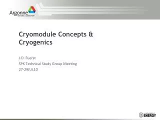
Pre-design of 9cell Cavity Test Cryogenic System Heat exchanger Horizontal test cryostat Vertical test cryostat
Vertical Test Cryostat FNAL vertical test cryostat
Progress of Vertical Test Cryostat • Components’ 3D models have been finished and the assembling model need to be checked; • Key materials have been counted; • Standard components’ selection and layouts are under doing and design ( throttling valves, safety valves, hose-burst valve, temperature sensors, pressure sensors, standard cryogenic connectors); • Key part heat exchanger is under design and need further discussion with FERMILAB; • The first version of drawings is planed to be finished at the end of this year;
Horizontal Test Cryostat • Single 9cell cavity horizontal test cryostat with length of 1800mm and diameter of 966mm; • Cross-section almost the same as EXFEL cryomodule; • A 300 mm He Gas-Return-Pipe (GRP) acting as support structure, together with 2 adjustable posts on top of the vacuum vessel. One post is the fixed-point, the other post can slide in longitudinal direction; • A 1.8 K forward line transferring single phase helium, a 1.8 K two phase line connected to the cavity helium vessels, a 4-8 K forward and return line, a 40/80 K forward and return line, and a warm-up/cool-down line with capillary to the bottom of cavity vessel; • Aluminum thermal shields with stiff upper parts for 4/8K and 40/80 K are attached to the support structure, with 10 layers and 30 layers of super-insulation (MLI) for 4/8K and 40/80 K respectively; • In the end of cryostat, there is a small helium vessel with a liquid level meter inside, which is connected with He GRP and 1.8K supplying line of 9cell cavity. The cavity can be kept in the 1.8K LHe by monitoring the liquid level meter.
Progress of Horizontal Test Cryostat • Structure design has been finished; • Model design is nearly finished; • POST support is under design; • Parts of components’ structure need to be improved; • The first version of drawings is planed to be finished at the end of this year.
Next Years’ Plan • Complete the thermal dynamic simulation analysis; • Finish the drawings of vertical Test cryostat and horizontal Test Cryostat and put into machining; • Complete the whole flow chart of the 9cell cavity test cryogenic system; • ………….